Installing horizontal units – WaterFurnace Envision (XL) User Manual
Page 8
ENVISION 7-25 TONS INSTALLATION MANUAL
9
Installing Horizontal Units
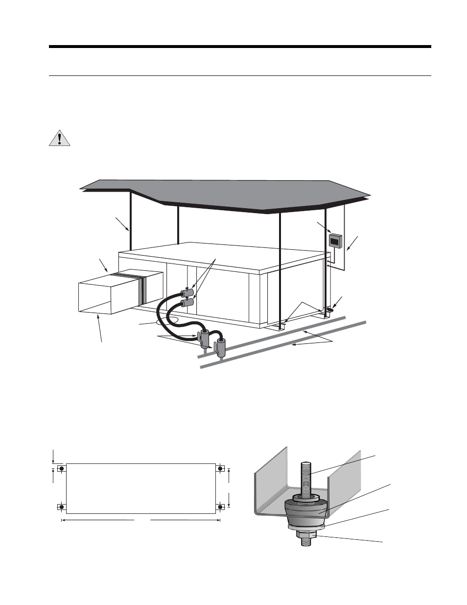
Mounting Horizontal Units
Units are available with side or end discharge in left-hand or right-hand return air configurations. Horizontal units are
normally suspended from a ceiling by four 1/2 in. diameter threaded rods. The rods are usually attached to the unit corners
by the bottom panel mounting channel and the mounting grommets furnished with each unit.
CAUTION: Do not use rods smaller than 1/2 in. diameter since they may not be strong enough to support the
unit. The rods must be securely anchored to the ceiling (the units are approximately 800 lbs.).
Top View
90.5
26.24
4.13
Figure 3: Mounting Hardware
Figure 2: Mounting Rod Layout
Ball Valves
Water Loop
Flexible Duct
Collar
1/2”
Threaded Rods
(4)
P/T Plugs
Hose Kits
Insulate supply
plenum and use at
least a 90° elbow
to reduce noise
Condensate
Drain
Connection
Power
Disconnect
Low
Voltage
Isolation
Grommets
(Included)
Figure 1: Typical Horizontal Application
Layout the threaded rods per the dimensions in Figure 2. Assemble the hangers to the unit as shown in Figure 3. Securely
tighten the brackets to the unit. When attaching the hanger rods to the bracket, a double nut is recommended since
vibration could loosen a single nut. The unit should be pitched approximately 1/2 in. towards the drain in both directions, to
facilitate condensate removal.
1/2 in. Threaded Rod
(not included)
Vibration
Isolator
Washer
(not included)
Hex Nuts
(not included)