Vortech 2000-2008 Honda S2000 User Manual
Page 44
P/N: 4HS020-010
©2008 Vortech Engineering, LLC
All Rights Reserved, Intl. Copr. Secured
21OCT08 v4.0 S2000(4HS020-010v4.0)
32
15. HOSE ATTACHMENTS/EXTENSIONS
A.
(2000-2005 Models only)
Connect the
lower end of the supercharger oil drain hose to
the previously installed fitting in the drain pan
using the supplied 90° x 1/2" swivel hose end.
Hose routing must be downhill with smooth
bends and must not have kinks, sharp bends or
uphill sections. Trim hose length if necessary.
Secure the drain hose to the oil pan fitting with
a #8 clamp.
B.
(2000-2005 Models only)
Connect the
supercharger oil feed line to the previously
installed flare fitting near the oil pressure send-
ing unit. Make a gentle forward loop around
and beneath the front crossmember. Secure the
hose with the tie-wraps provided, routing it
away from chaffing and/or sharp objects.
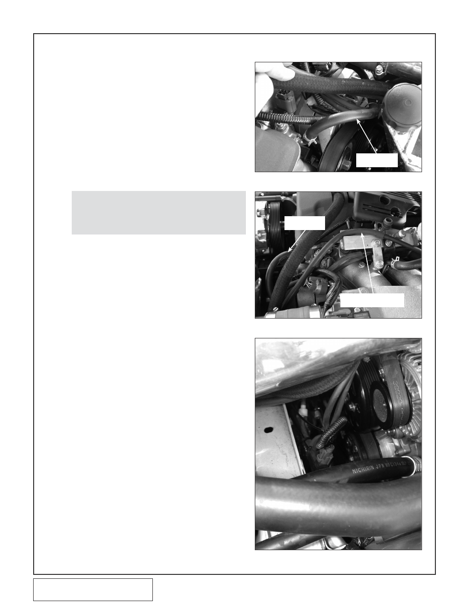
C.
Attach the supplied piece of 1/4" x 16" long
hose to the cylinder head coolant port that was
previously connected to the factory vacuum/
coolant tubing junction removed in Step 1.
Attach the remaining end of the hose to the cor-
responding port on the throttle body. Secure
both ends with the previously removed factory
clamps. (See Fig. 15-a, 15-b.)
D.
Install the length of 1/2" x 36" hose to the valve
cover vent barb. Connect the opposite end to
the 1/2" brass barb located on the supercharger
inlet elbow. Trim the length if necessary.
E.
(2000-2005 Models only)
Attach the
length of supplied 1/4" vacuum hose to the fit-
ting on the cover of the Vortech compressor
bypass valve. Route the hose over near the fuel
rail. Install the supplied 5/32" -1/4" hose reducer
into the end of the 1/4" hose. Splice one of the
supplied 5/32" brass TEEs into the fuel pressure
regulator/FMU signal hose. Attach the compres-
sor bypass vacuum hose to the remaining leg of
the 5/32 TEE using a short piece of 5/32" vacu-
um hose. (See Fig. 15-b.)
F.
(2006-2008 Models only)
Attach the
length of supplied ¼” vacuum line to the fitting
on the cover of the Vortech compressor bypass
valve. Route the hose over toward the brake
boost located on the driver’s side firewall. Install
the 1/4"-5/32 reducer onto the open end of the
line. This line will be connected in a later step.
G.
Reconnect the two factory vacuum hoses that
were removed in Step 1. Use the supplied
lengths of 5/32" tubing for extensions if required.
H.
(Not on 2006-2008 Models)
Re-attach
the pressure solenoid (that was removed in
Step 1) to the harness and vacuum hoses. Use
a tie-wrap to secure the unit down toward the
crossmember and away from the crank pulley.
(See Fig. 15-c.)
NOTE: Use only clean engine oil on the pipe
threads. teflon tape or pipe sealant is not
recommended as it might loosen and
cause blockage of the small oil feed orifice
resulting in possible supercharger failure.
Fig. 15-a
Fig. 15-b
Fig. 15-c
SUpplied 1/4"
HoSe x 16"
coMpreSSor bypaSS
VacUUM HoSe
SUpplied 1/4"
HoSe x 16"