Vortech 2000-2008 Honda S2000 User Manual
Page 28
P/N: 4HS020-010
©2008 Vortech Engineering, LLC
All Rights Reserved, Intl. Copr. Secured
21OCT08 v4.0 S2000(4HS020-010v4.0)
16
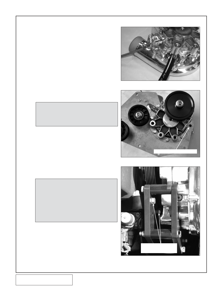
Secure with a #8 hose clamp. Make sure that
the hose clamp housing is clocked down
toward the supercharger so that it will not
cause interference with the supercharger
mounting plate that is to be installed. (See
Fig. 8-j.)
H. (2000-2005 Models Only) Remove the
blue plastic dust cap located on the brass oil
feed nozzle on the side of the supercharger.
Thread the supplied steel 1/8" NPT x 45° x
–4JIC fitting into the supercharger oil feed
nozzle. Carefully tighten and clock the 45° fit-
ting as shown in Figs. 8-j, 8-k. Use caution
when tightening the oil feed fitting, as the
brass nozzle may be broken if care is not
exercised. Connect the supplied oil feed line
to the flare fitting. Temporarily cover the open
end from debris until the connection is made
to the engine in step 15.
I.
Attach the supercharger unit to the mounting
plate as shown using the five supplied 3/8-16
x 1.25" screws with AN washers. The sixth
supercharger mounting hole should remain
empty at this time. (Refer back to Fig. 8-e,
and Fig. 8-k.)
J.
Using two of the supplied 3/8-16 x 1.25"
screws with AN washers, attach the upper
supercharger support plate to the super-
charger mounting block as shown in Figs. 8-l,
8-m. Thread the screws down until the heads
almost touch the plate/washers. Do not tight-
en the screws at this time.
K. From the back side, slide the supplied 3/8-16
x 3.5" screw and AN washer through the top
hole (refer to Figs. 8-n, 8-o) of the upper sup-
port plate and into one of the supplied Ø.875
O.D. x 1.858" long spacers. Loosely mount
the support plate assembly with spacer onto
the supercharger and previously assembled
main supercharger plate.
NOTE: Use only clean engine oil on the pipe
threads. teflon tape or pipe sealant is not
recommended as it might loosen and
cause blockage of the small oil feed orifice
resulting in possible supercharger failure.
NOTE: when directed, it is important to follow the
suggestion: “do not tighten the screws”.
Failure to follow this direction will result in
bracket misalignment and the possibility of
the Vtec solenoid not maintaining a prop-
er seal. thread the applicable screws and
nuts in until the head almost touches down
(.01-.02" clearance). this will allow the
bracket to properly align itself to the
engine and other components in the
assembly during installation.
8. SUPERCHARGER MOUNTING BRACkET/PLATE INSTALLATION, cont’d.
Fig. 8-j (2000-2005 only)
Fig. 8-k
Fig. 8-l
no FaStener Here at tHiS tiMe
3/8-16 x 1.25
ScrewS witH an waSHerS
(do not tigHten)