Vortech 2000-2008 Honda S2000 User Manual
Page 35
P/N: 4HS020-010
©2008 Vortech Engineering, LLC
All Rights Reserved, Intl. Copr. Secured
21OCT08 v4.0 S2000(4HS020-010v4.0)
23
8. SUPERCHARGER MOUNTING BRACkET/PLATE INSTALLATION, cont’d.
Fig. 8-x
spacer and into the center 12 mm boss
located on the supercharger cover.
4. Two 3/8-16 x 1.25" screws with AN wash-
ers that attach the supercharger support
plate to the supercharger mounting block.
5. M10 x 1.25 x 115 screw through the front
of the supercharger mounting plate and
into the factory idler pulley mount on the
front cover.
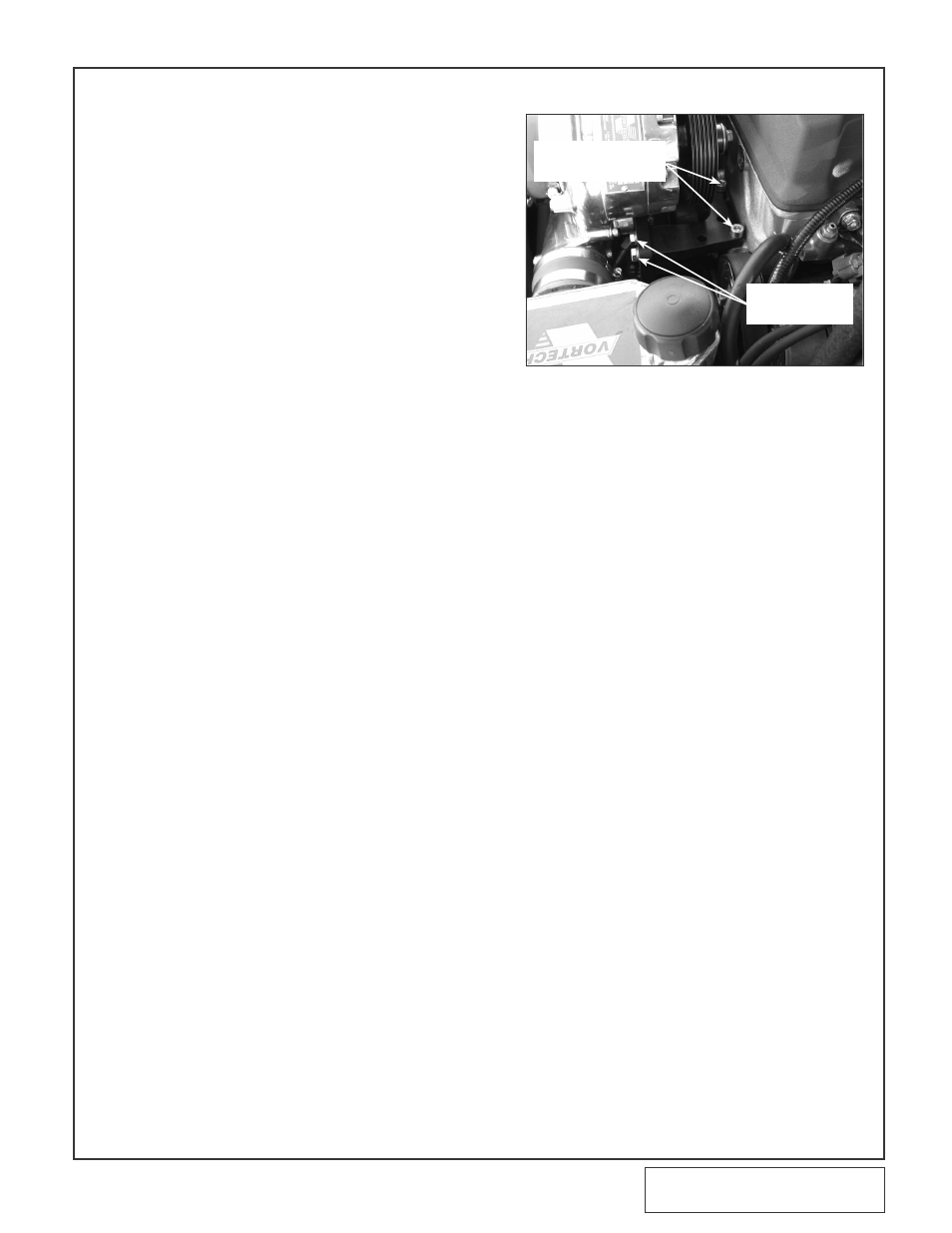
6. Two 5/16-18 x 1.0" screws through the
supercharger mounting plate and into the
lateral support.
7. Two M8 x 1.25 x 45 socket head screws
through the lateral support mounting plate,
front corner of the cylinder head and into
the front cover.
8. Three 3/8-24 x 3.5" screws running
through the main mounting plate, Ø.875
O.D. x 1.858" long spacers and into the
threaded steel inserts that are pressed into
the back side of the support plate.
9. Two M6 nuts that are threaded onto the
two studs inserted into the front of the
engine.
X.
Repeat the sequence above with final torqu-
ing of all hardware.
Y.
Reconnect the previously removed VTEC wir-
ing connections.
Z.
(
NOT ON
2006-2008 Models) Reattach
the plastic vacuum canister to the backside of
the front crossmember (located in front of the
engine) using the factory screw that was
removed in step 1. Make sure that there is
enough clearance between the vacuum hose
and the crank pulley.
AA. (2006-2008 Models only) Secure the
stainless steel oil service line away from hot
or morning assemblies that may damage it.
Locate the line so that it maybe easily
accessed for service.
two 5/16-18 x 1"
ScrewS witH
an waSHerS
two M8 x 1.25 x 45
Socket Head ScrewS
(no waSHerS)