Vortech 2000-2008 Honda S2000 User Manual
Page 41
P/N: 4HS020-010
©2008 Vortech Engineering, LLC
All Rights Reserved, Intl. Copr. Secured
21OCT08 v4.0 S2000(4HS020-010v4.0)
29
13. CHARGE AIR COOLER INSTALLATION, cont’d.
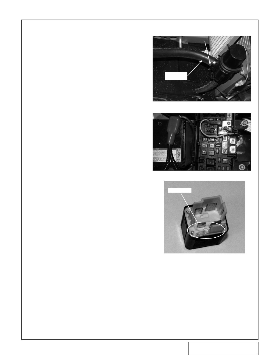
L.
Attach an 16 Ga. insulated female slide con-
nector to the yellow wire attached to the sup-
plied relay. Route the yellow wire from the
relay to the power distribution box located in
front of thebattery. Following Fig. 13-g, route
the wire up along the factory wires.
M. Remove the factory heater motor relay locat-
ed in the underhood fusebox and modify to
accept the electrical power tap as shown in
Fig. 13-h. Reinstall the relay with the power
tap. Connect the yellow wire to the power tap.
N. Attach the black wire from the supplied relay
to a suitable ground.
O. Route the red wire from terminal #87 on the
supplied relay down to the water pump.
Install a female insulated slide connector onto
the wire and connect to the blue/green (posi-
tive) wire on the water pump.
P.
Cut the supplied fuse holder wire and install
the 12 GA ring terminal on one end and the
12 GA. solderless connector onto the other.
Connect the #30 wire on the supplied relay to
the solderless connector attached to the fuse
holder. Connect the ring terminal to the posi-
tive side of the battery and install the provid-
ed fuse.
Q. Using one of the 4 X 12 3/4" 90° molded
hoses attach the short leg to the discharge of
the water pump and insert a 3/4" hose union
into the long leg. Locate the 3/4" 150° molded
hose and attach the long leg to the other end
of the 3/4" hose union and route and attach
the other end of the 150° molded hose to the
lower port on the front mounted water cooler.
Secure each connection with nylon clamps
provided.
R. Temporarily install the water tank mounting
bracket onto the water reservoir using the
1/4" hardware (see Fig. 13-k). Mock the water
reservoir up as shown and mark the location
on the vehicles frame (passenger side, outer
frame rail) where the #10 self-tapping screws
are to be located. Remove the 1/4" hardware
attaching the bracket to the reservoir. Secure
the bracket to the vehicle using the self-tap-
ping screws. (See Fig. 13-j.)
S.
Install the two remaining 90° brass fittings
into the water reservoir using a small amount
of thread sealant. Attach one end of the
remaining Ø 3/4" hose to the top of the water
reservoir and secure with a clamp.
T.
Permanently attach the water reservoir to the
mounting bracket using the 1/4" hardware.
U. Route the upper reservoir hose into the
engine compartment (Fig. 13-k) under the
radiator fan and then up between the radiator
fan and the condenser fan finally connecting
it to the passenger side fitting on the charge
air cooler. Secure the hose with one of the
provided clamps.
Fig. 13-f
Fig. 13-g
Fig. 13-h
water pUMp
oUtlet HoSe
ModiFy Here