Vortech 2000-2008 Honda S2000 User Manual
Page 24
P/N: 4HS020-010
©2008 Vortech Engineering, LLC
All Rights Reserved, Intl. Copr. Secured
21OCT08 v4.0 S2000(4HS020-010v4.0)
12
8. SUPERCHARGER MOUNTING BRACkET/PLATE INSTALLATION
A.
Detach the factory wiring harness from the rear
of the front crossmember for mounting bracket
clearance. Push the harness down toward the
steering rack.
B.
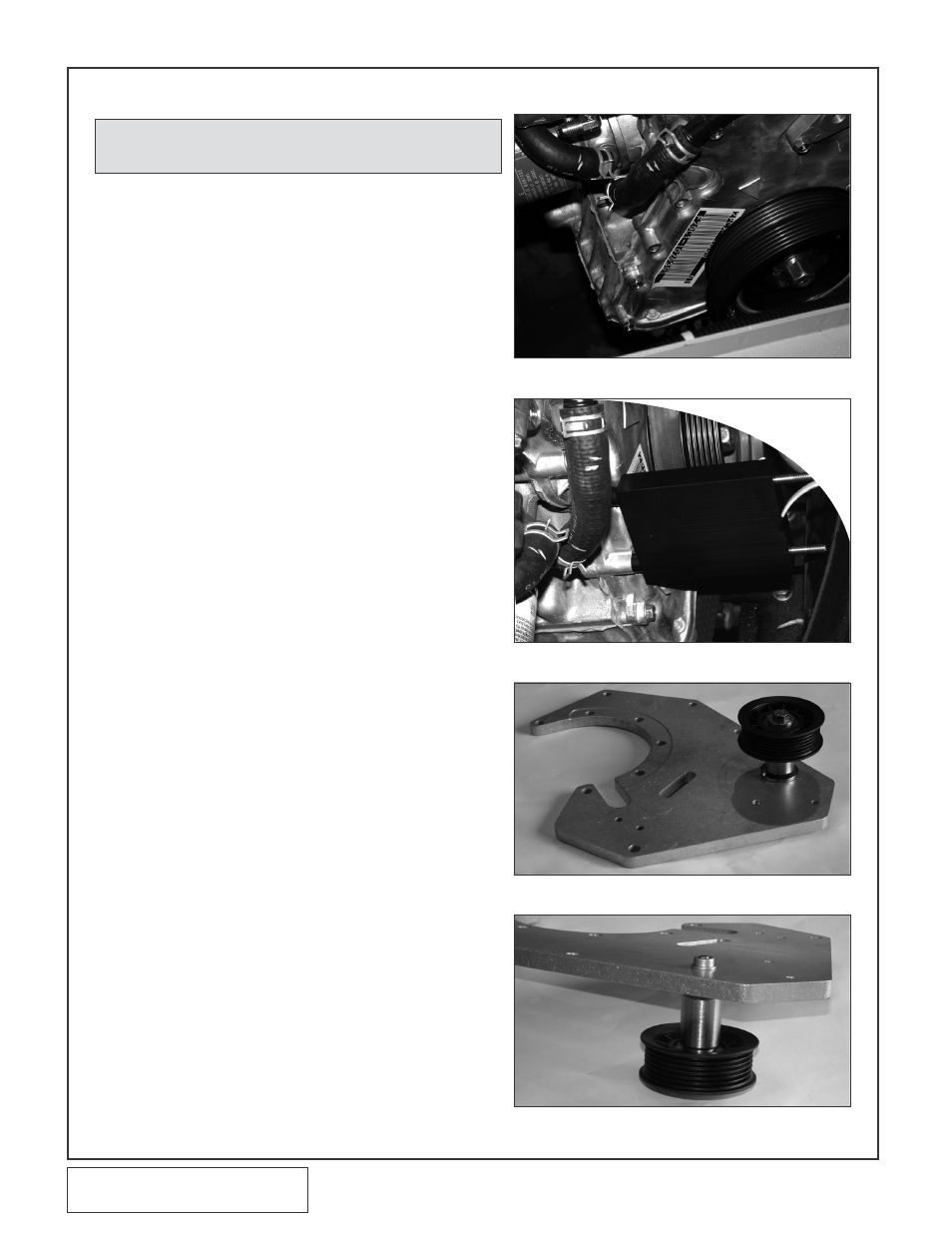
Remove the two factory M6 x 1.0 screws from
the passenger side front of the engine near the
crank pulley at the location shown in Fig. 8-a.
C.
Locate the lower supercharger plate spacer.
This is a .75" thick aluminum spacer that is 2.9"
wide x 4.05" tall with two 1/2" round protrusions
machined into one end. Slide the two supplied
10 mm studs through the holes in the lower
plate spacer. With the studs located loosely
through the lower plate spacer, thread the two
studs into the front cover as shown in Figs. 8-b,
8-n, 8-o. This step must be done as described
because of the limited space available in the
engine compartment. Use a drop of blue Loctite
on the threads of the studs before threading
them into the engine. Tighten the studs into the
front of the engine by using a stud wrench, or
by temporarily threading two nuts on the end of
each stud and torquing. Remove the nuts from
the ends of the studs.
D.
Attach the supplied 6 grooved idler pulley to the
main supercharger mounting plate as shown in
Figs. 8-c, 8-d, 8-e, 8-f. Slide one of the supplied
3/8-24 x 3.5" screws through the machined
bearing pilot, 6 groove idler pulley and steel
idler spacer (1.772" effective length x Ø.406"
through hole). Attach the complete assembly to
the aluminum mounting plate by threading the
3/8-24 x 3.5" screw through the plate and into
the threaded steel insert that is pressed into the
plate.
E.
Attach the belt tensioner adjustment screw, ten-
sioner arbor and adjustment screw locator block
to the supercharger mounting plate as shown in
Figs. 8-e, 8-f, 8-g, 8-h, 8-i. Secure the assembly
to the plate by threading the two 1/4-20 x .75"
socket head screws through the plate and into
the adjustment screw locator block as shown.
Make sure the locator block is positioned as
shown in Fig. 8-h or you will experience oil feed
line clearance issues.
F.
Slide the supplied smooth idler pulley and steel
idler spacer (1.772" effective length x Ø.515"
through hole) over the tensioner arbor that was
previously installed onto the mounting plate.
Install the 12 mm washer and 1/2-20 jam lock
nut over the idler and arbor. Do not tighten the
nut at this time. (See Fig. 8-f.)
G.
(2000-2005 Models only) Remove the blue
plastic dust cap located on the 1/2" oil drain fit-
ting on the bottom of the supercharger. Attach
the supplied 1/2" x 18" fabric braided oil drain
hose to the supercharger drain fitting.
Fig. 8-a
Fig. 8-b
Fig. 8-c
Fig. 8-d
NOTE: Use a drop of blue loctite on all fastener threads
prior to assembly.