Air inlet – Vortech 2003-2004 Mustang Mach 1 User Manual
Page 32
P/N: 4FR020-010
©2004 Vortech Engineering, LLC
All Rights Reserved, Intl. Copr. Secured
23AUG04 86-93 4V Mus. Cobra(4FR v3.1)
P/N: 4FR020-010
©2004 Vortech Engineering, LLC
All Rights Reserved, Intl. Copr. Secured
23AUG04 86-93 4V Mus. Cobra(4FR v3.1)
20
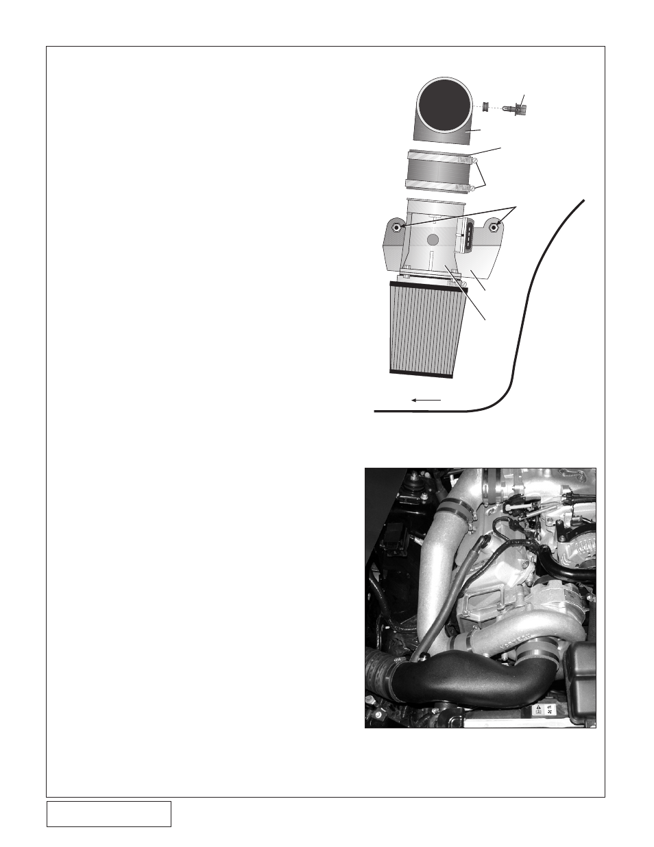
10. AIR INLET
A. Using the supplied 1/4-20 hardware, mount the
supplied MAF meter to the Vortech MAF bracket
and secure (see Fig. 10-a for orientation). Remove
the factory MAF screen before attaching the meter
to the new MAF bracket.
B. Attach the supplied K & N air filter, 4" sleeve, 90°
x 3-1/2" x 4" elbow and #64 hose clamps to the
MAF and secure.
C. Mach 1 Models Only: Cut the outer two wires
attached to the MAF harness plug approximately
2" from the MAF connector. (See Fig. 10-h.)
Connect the gray with red stripe wire coming from
the main harness to the red wire in the supplied
IAT sensor harness using solder and the supplied
shrink sleeve.Connect the gray wire coming from
the main harness to the black/brown wire on the
supplied IAT sensor harness using solder and the
supplied shrink sleeve.
D. Insert the factory air temperature sensor into the
rubber grommet located on the side of the 90°
elbow. Lubricate it for easier fit.
E. Working from beneath the vehicle, remove the
two factory nuts and washers from the passenger
side lower fender valence. Mount the MAF/bracket
assembly onto the existing studs using the same
washers and nuts originally removed. (See Fig.
10-a).
VIEW FROM INSIDE ENGINE COMPARTMENT
(Steel inner fender not shown for ease of description)
Fig. 10-a
F. Using a #52 hose clamp, connect the piece of
3-1/2" flex hose to the elbow attached to the MAF
meter and route it through the opening in the right
side inner fender toward the supercharger. Make
sure that the 3-1/2" flex hose does not contact
or rub on the edge of the inner fender opening
(eventual hose failure will result if the hose is not
properly routed).
G. Route the factory temperature sensor and MAF
sensor connectors out through the inner fender
opening. Reattach the connectors to the relocated
sensors.
H. Connect the supplied molded inlet duct onto the
supercharger inlet (see Fig. 10-b) using the 3-1/2"
sleeve and #56 hose clamps provided.
I. Attach the supplied 1" x 90° rubber hose and #16
hose clamp to the 3/4" x 1" straight hose fitting
located on the inlet duct. (See Fig. 10-c.)
J. Connect the previously installed 3-1/2" flex hose
to the inlet duct and secure with the #52 clamp.
K. Install the supplied length of 3/4" hose from the
inlet duct to the crankcase breather fitting (see
Fig. 10-d). Trim hose length as necessary.
L. Take the supplied 5/8" rubber end cap and install
it on the 5/8" boss on the molded inlet duct.
FRONT
INSIDE
FRONT
PASSENGER
FENDERWELL
#64 CLAMPS
SLEEVE
ALUMINUM
REDUCER ELBOW
FACTORY
STUDS & NUTS
INTAKE AIR
TEMPERATURE
SENSOR
MAF
BRACKET
MAF
METER
Fig. 10-b