1999 models only – Vortech 2003-2004 Mustang Mach 1 User Manual
Page 21
P/N: 4FR020-010
©2004 Vortech Engineering, LLC
All Rights Reserved, Intl. Copr. Secured
23AUG04 86-93 4V Mus. Cobra(4FR v3.1)
P/N: 4FR020-010
©2004 Vortech Engineering, LLC
All Rights Reserved, Intl. Copr. Secured
23AUG04 86-93 4V Mus. Cobra(4FR v3.1)
8.1 MAIN BRACKET ASSEMBLY/DRIVE BELT - 1999 Models, cont'd.
E. Loosen and remove the three nuts securing the
factory coolant reservoir to the car. Temporarily
move aside to provide room to mount the super-
charger. (Do not remove any hoses or connectors
from reservoir.)
F. Remove the factory flanged water pump pulley
and replace with the supplied non-flanged pul-
ley.
G. Following Figs. 8.1-c & 8.1-d, attach the
supercharger/aluminum bracket assembly with
the Vortech idler pulley and idler spacer to the
alternator stud and front cover using the sup-
plied 8mm hardware. Route the new, longer belt
around the outside of the supercharger drive pul-
ley, then around the inside of the Vortech idler.
Finish routing the belt around all of the pulleys,
except for the water pump. Make sure that the
Vortech idler pulley and spacer (located against
the alternator base), are seated and located in
their proper positions before tightening down the
bolts (see Fig. 8.1-e for belt routing).
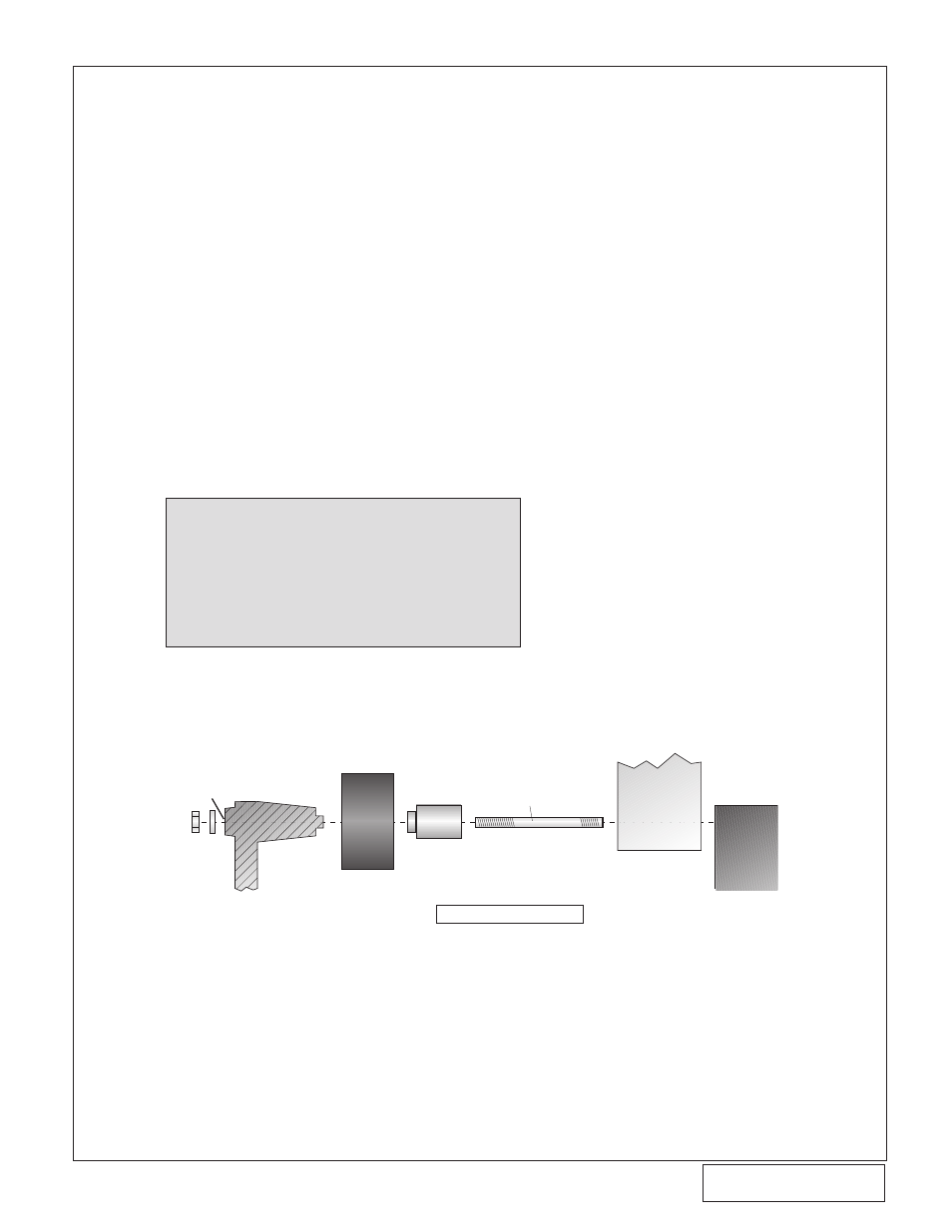
VIEW FROM DRIVER'S SIDE
VORTECH
IDLER PULLEY
VORTECH
SUPERCHARGER
MOUNTING BRACKET
STEEL IDLER
SPACER
ALTERNATOR
BOSS
HOLE POSITION #3
(SEE GRAPHIC ON
NEXT PAGE)
SUPPLIED 8mm STUD
(THREAD COMPLETELY
INTO BLOCK UNTIL
THREADS STOP)
ENGINE
BLOCK
Fig. 8.1-d
NOTE: When installing the Vortech idler pulley,
make sure that the bearing shim located
between the bearings in the pulley allows
for complete insertion of the idler spacer
and bracket pilot. Install the steel idler
spacer into the idler pulley and verify that
the shim is not interfering with the idler
spacer pilot.
1999 Models Only
9