Velodyne SC-IWBB User Manual
Page 15
www.velodyne.com
SC-IW Installation Manual - 9
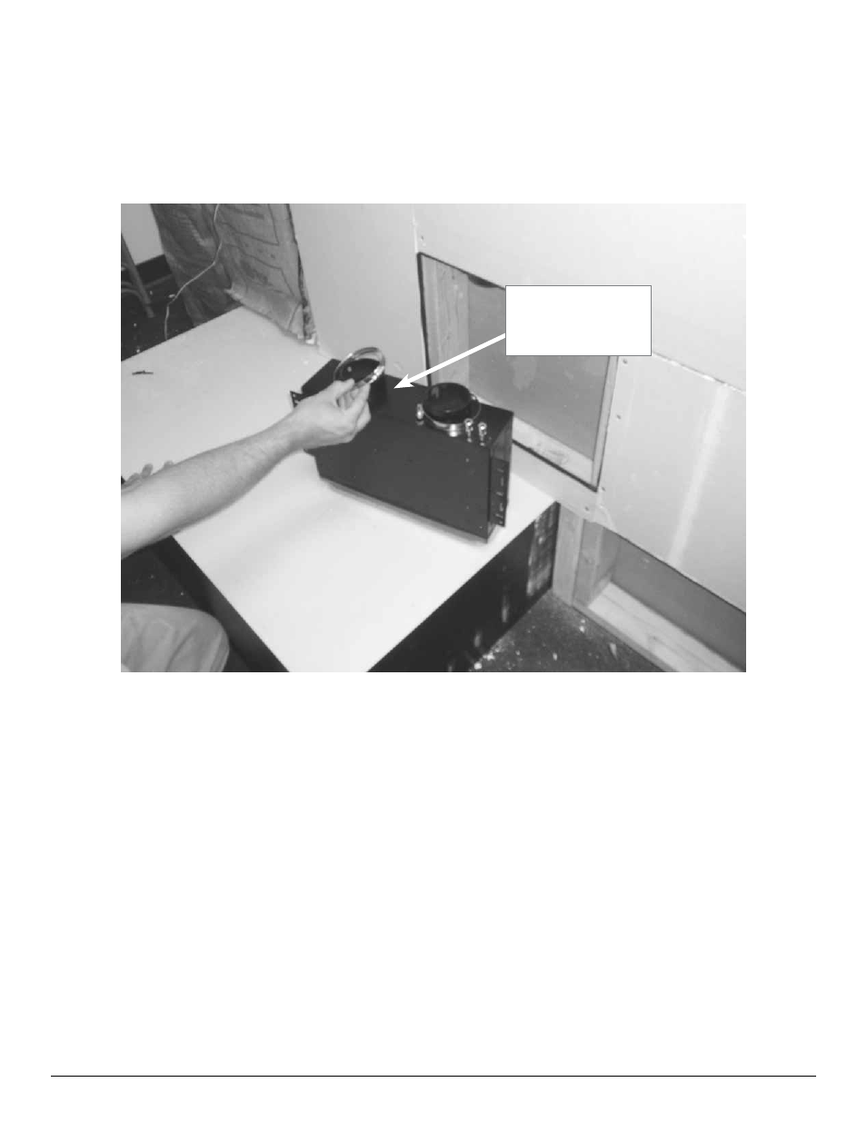
Step 8 - Place Clamp Rings on Driver Module
Remove the two clamp rings from the packaging and place a clamp ring onto each of the bottom edges of the
tubes.
Note: The position of the clamp ring is critical. Make sure that the screw section of the ring is on either side of
the tube and not on the front or the back. Please see picture below.
Figure 6: Clamp Ring Placement
Screw must
face outward
See also other documents in the category Velodyne Audio:
- CHT-Q Series (26 pages)
- CHT-R Series (24 pages)
- DEQ-R Series (26 pages)
- Digital Drive Series (54 pages)
- Digital Drive 1812 Signature Edition (57 pages)
- Digital DrivePLUSSeries (42 pages)
- Digital DrivePLUSSeries (40 pages)
- Digital DrivePLUSSeries (19 pages)
- EQ-Max Series (24 pages)
- Impact Series (20 pages)
- MicroVee (24 pages)
- MiniVee Series (20 pages)
- Optimum Series (28 pages)
- SC-602 Amplifier (27 pages)
- SC-ICG (12 pages)
- SC-IF/IC (14 pages)
- SMS-1 (49 pages)
- SPL-800i (20 pages)
- SPL-Ultra Series (22 pages)
- SubContractor Series (30 pages)
- VX-11 (16 pages)
- WiConnect (24 pages)
- WiConnect (19 pages)
- Wi-Q (29 pages)
- CHT Front Row System (6 pages)
- CHT-15 (12 pages)
- Deco (12 pages)
- DF-10sc (6 pages)
- DLS-3500 (6 pages)
- DLS-R Series (9 pages)
- DPS 10-12 Series (17 pages)
- DS-10 (49 pages)
- FSX-12 (8 pages)
- HGS 10 (10 pages)
- HGS-12X (19 pages)
- HGS-15 THX Ultra 2 (10 pages)
- HGS-15X THX Ultra 2 (20 pages)
- SPL-800 (8 pages)
- SPL-800 Series II (20 pages)
- SPL-R Series (17 pages)
- VA-1250X (8 pages)
- VA-806 (6 pages)
- VA-907.2 (6 pages)
- VDR Series (18 pages)