Velodyne SC-IWBB User Manual
Page 11
www.velodyne.com
SC-IW Installation Manual - 5
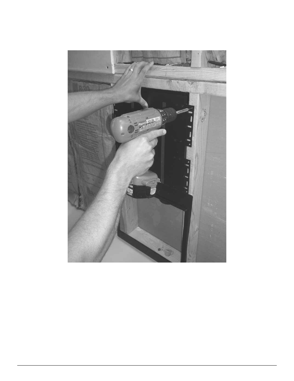
Step 2 - Install Back Box
Once the mudring is stapled into place, the back box should be installed using eight of the phillips drive flat
head screws included in the package. when installing the back box, the mudring should be aligned to the white
line on the cabinet. Once the mudring and the back box are aligned, install the back box as shown.
Figure 2: Install Back Box
See also other documents in the category Velodyne Audio:
- CHT-Q Series (26 pages)
- CHT-R Series (24 pages)
- DEQ-R Series (26 pages)
- Digital Drive Series (54 pages)
- Digital Drive 1812 Signature Edition (57 pages)
- Digital DrivePLUSSeries (42 pages)
- Digital DrivePLUSSeries (40 pages)
- Digital DrivePLUSSeries (19 pages)
- EQ-Max Series (24 pages)
- Impact Series (20 pages)
- MicroVee (24 pages)
- MiniVee Series (20 pages)
- Optimum Series (28 pages)
- SC-602 Amplifier (27 pages)
- SC-ICG (12 pages)
- SC-IF/IC (14 pages)
- SMS-1 (49 pages)
- SPL-800i (20 pages)
- SPL-Ultra Series (22 pages)
- SubContractor Series (30 pages)
- VX-11 (16 pages)
- WiConnect (24 pages)
- WiConnect (19 pages)
- Wi-Q (29 pages)
- CHT Front Row System (6 pages)
- CHT-15 (12 pages)
- Deco (12 pages)
- DF-10sc (6 pages)
- DLS-3500 (6 pages)
- DLS-R Series (9 pages)
- DPS 10-12 Series (17 pages)
- DS-10 (49 pages)
- FSX-12 (8 pages)
- HGS 10 (10 pages)
- HGS-12X (19 pages)
- HGS-15 THX Ultra 2 (10 pages)
- HGS-15X THX Ultra 2 (20 pages)
- SPL-800 (8 pages)
- SPL-800 Series II (20 pages)
- SPL-R Series (17 pages)
- VA-1250X (8 pages)
- VA-806 (6 pages)
- VA-907.2 (6 pages)
- VDR Series (18 pages)