Wiring the terminal block – Spectrum Controls 140 EHC 204 00sc User Manual
Page 19
Quantum Series 140 EHC 204 00sc 140 EHC 208 00sc
20
Wiring the Terminal Block
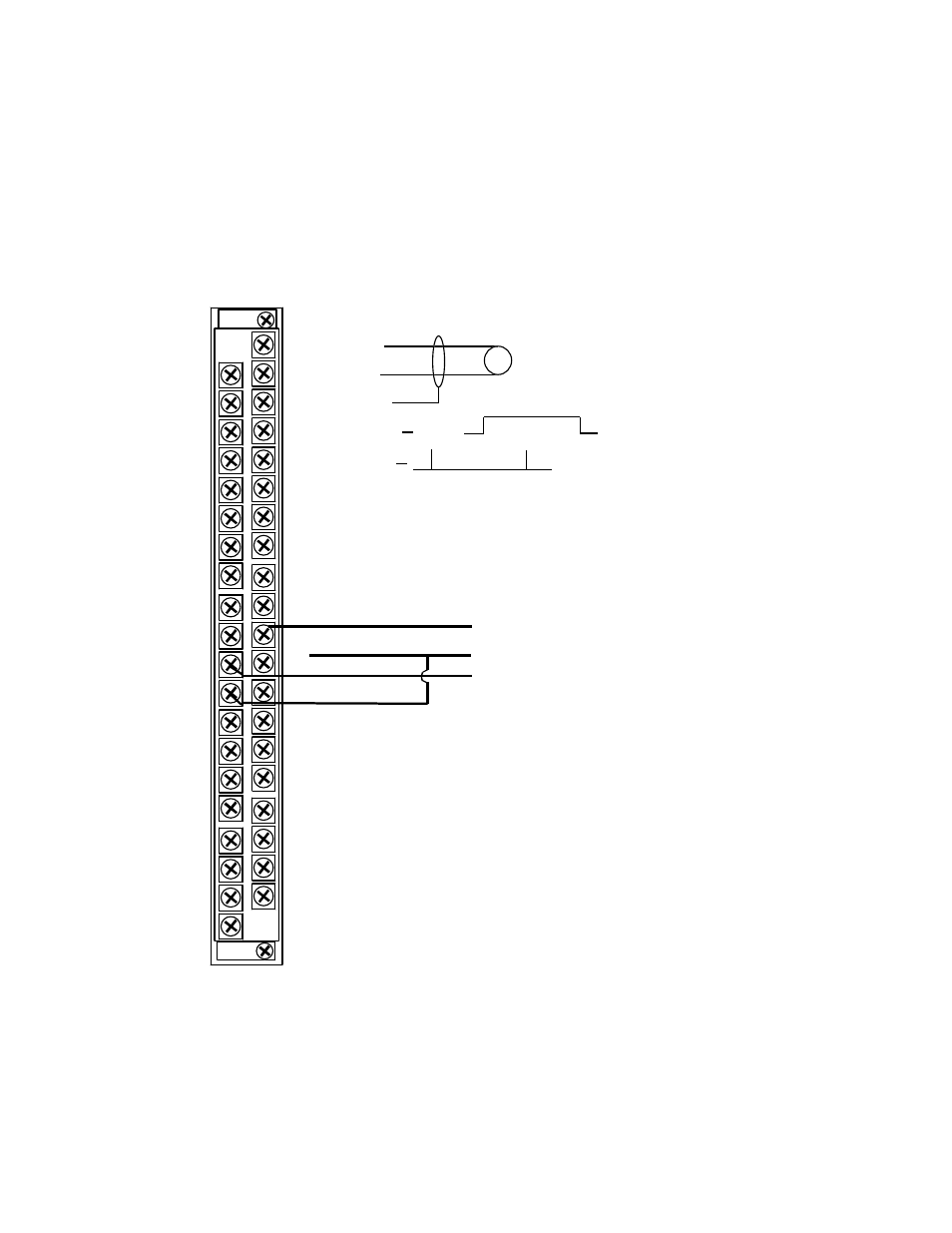
The module terminal block has eight shield terminals provided as frame ground connections for input wire
shielding. It also provides eight external encoder disable pins used to externally gate each input. A low input
allows each channel (or channel pair) to operate. There are also 8 counter enable lines that are compatible with 5,
12, and 24 VDC inputs. If pulled high with one of these inputs, a channel (or channel pair) is disabled.
Pin 1 C hannel 1 H i
Pin 3 C hannel 1 L o
Pin 5 C hannel 1 Shie ld
Pin 7 C hannel 1 E na ble
Pin 9 C hannel 1 G ate
Pin 11 C hannel 3 H i
Pin 15 C ha nnel 3 Sh ield
Pin 17 C ha nnel 3 En able
Pin 13 C ha nnel 3 Lo
Pin 19 C ha nnel 3 G a te
P in 21 C ha nnel 5 H i
Pin 25 C ha nnel 5 Sh ield
Pin 27 C ha nnel 5 En able
Pin 23 C ha nnel 5 Lo
Pin 29 C ha nnel 5 G a te
Pin 31 C ha nnel 7 H i
P in 35 C ha nnel 7 Shield
P in 37 C ha nnel 7 E nable
Pin 33 C hannel 7 L o
P in 39 C ha nnel 7 G ate
C hannel 2 H i Pin 2
C hannel 2 L o P in 4
C hannel 2 Shie ld P in 6
C hannel 2 E nable P in 8
C hannel 2 G ate Pin 1 0
C ha nnel 4 H i Pin 1 2
C hannel 4 L o Pin 1 4
C h anne l 4 Shield Pin 1 6
C ha nnel 4 E nable Pin 1 8
C ha nnel 4 G a te P in 20
C hannel 6 H i P in 22
C hannel 6 L o Pin 2 4
C h anne l 6 Shield Pin 2 6
C ha nnel 6 E nable Pin 2 8
C hannel 6 G ate Pin 3 0
C ha nnel 8 H i Pin 3 2
C hannel 8 L o Pin 3 4
C hannel 8 Shield P in 36
C ha nnel 8 E nable Pin 3 8
C hannel 8 G ate Pin 4 0
24VDC
+
-
Typical
Meter Input
A input
B input
Common
Typical Quadrature
Encoder Input
Off On
Off
1- On
0 - Off
Each terminal accepts up to two wires, with the restrictions noted in the following table (for shielded, twisted-pair
cable).