Spectrum Controls 1769sc-IT6I User Manual
Page 62
C-2
Compact™ IO Isolated Thermocouple Module
User’s Manual Pub. 0300244-01 Rev. A
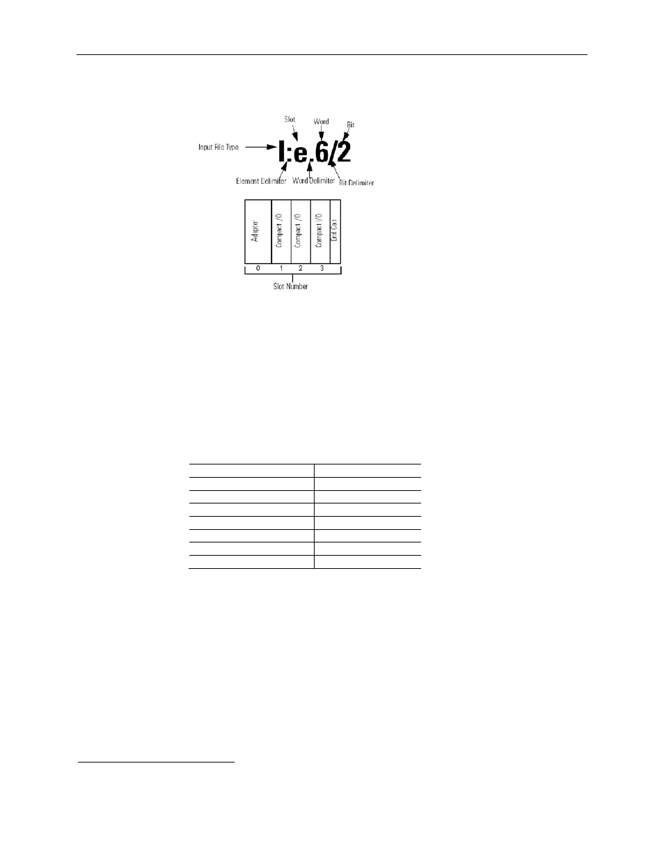
For example, to obtain the general status of channel 2 of the module located in slot e, use
address I:e.6/2.
Note: The end-cap does not use a slot address.
C.1.1 1769sc-IT6I Configuration File
The configuration file contains information you use to define the way a specific channel
functions. The configuration file is explained in more detail in Configuring Channels on
page 4-2.
The configuration file is modified using the programming software configuration screen.
For an example of module configuration using RSLogix 500, see Configuring the
1769sc-IT6I in a MicroLogix 1500 System on page C-2.
Table C-1 (Software Configuration Channel Defaults)
9
Parameter Default
Setting
Filter Frequency
10 Hz
Display CJC Temperature No
Open-Circuit Response
Upscale
Temperature Units
C˚
Input Type
J Type Thermocouple
Data Format
Raw/Proportional
Disable/Enable Channel
Enable
Section C.2
Configuring the
1769sc-IT6I in a
MicroLogix 1500
System
This example takes you through configuring your 1769sc-IT6I Isolated thermocouple/mV
input module with RSLogix 500 programming software, assumes your module is
installed as expansion I/O in a MicroLogix 1500 system, and that RSLinx™ is properly
configured and a communications link has been established between the MicroLogix
processor and RSLogix 500.
9
May be overridden by the software.