Spectrum Controls 1769sc-IT6I User Manual
Page 19
Chapter 2: Quick Start for Experienced Users
2-5
User’s Manual Pub. 0300244-01 Rev. A
•
Ground the shield drain wire at one end only. The preferred location is as
follows.
o
For grounded thermocouples or millivolt sensors, this is at the sensor
end.
o
For insulated/ungrounded thermocouples, this is at the module end.
Contact your sensor manufacturer for additional details.
•
Refer to Industrial Automation Wiring and Grounding Guidelines, Allen-
Bradley publication 1770-4.1, for additional information.
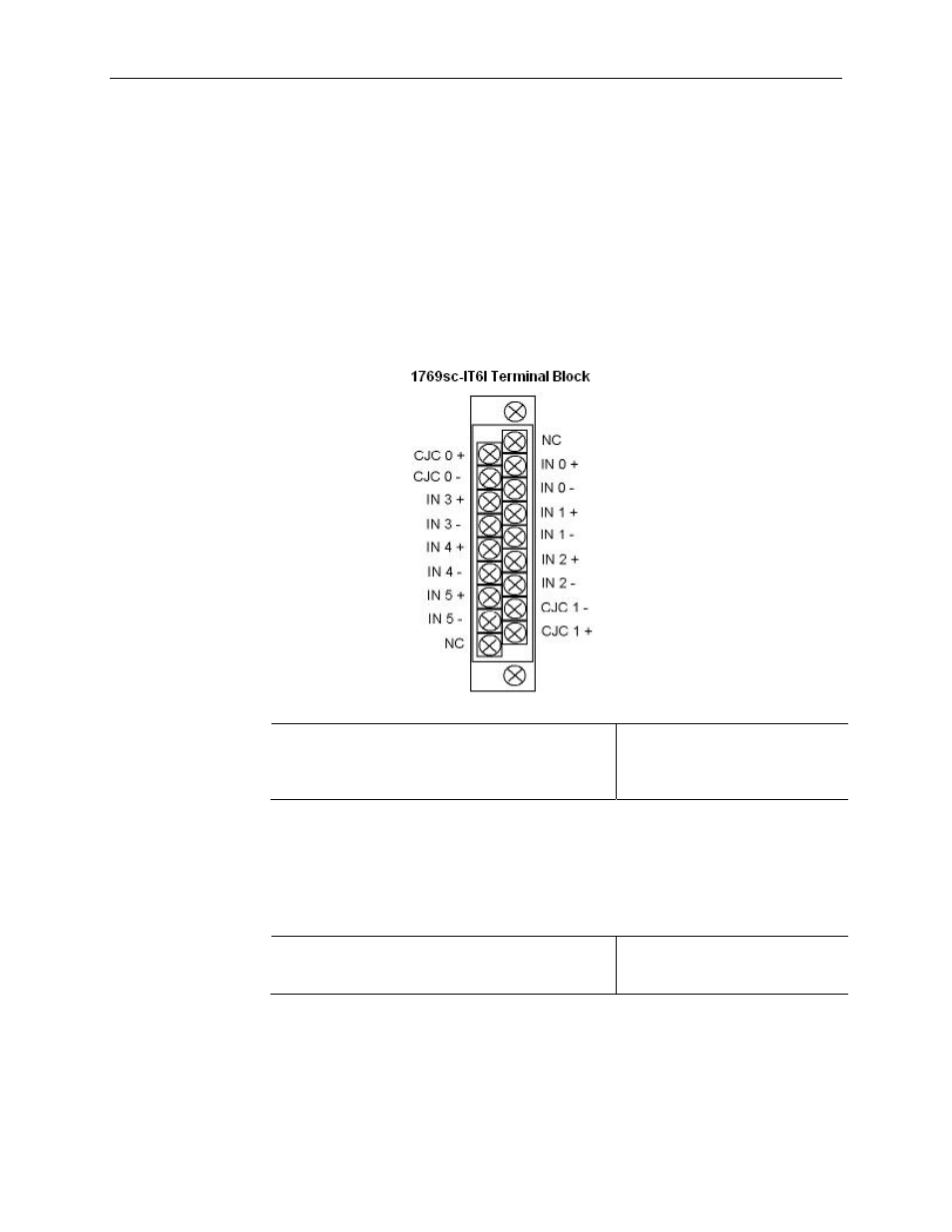
The terminal connections with CJC sensors are shown below:
Step 4: Configure the module.
Reference
Chapter 4
(Module Data, Status, and
Channel Configuration)
The configuration file is typically modified using the programming software compatible
with your controller. It can also be modified through the control program, if supported
by the controller. See Channel Configuration on page 4-3 for more information.
Step 5: Go through the startup
procedure.
Reference
Chapter 5(Diagnostics and
Troubleshooting)
1)
Apply power to the controller system.
2)
Download your program, which contains the thermocouple module
configuration settings, to the controller.