Spectrum Controls 1769sc-IT6I User Manual
Page 32
3-12
Compact™ IO Isolated Thermocouple Module
User’s Manual Pub. 0300244-01 Rev. A
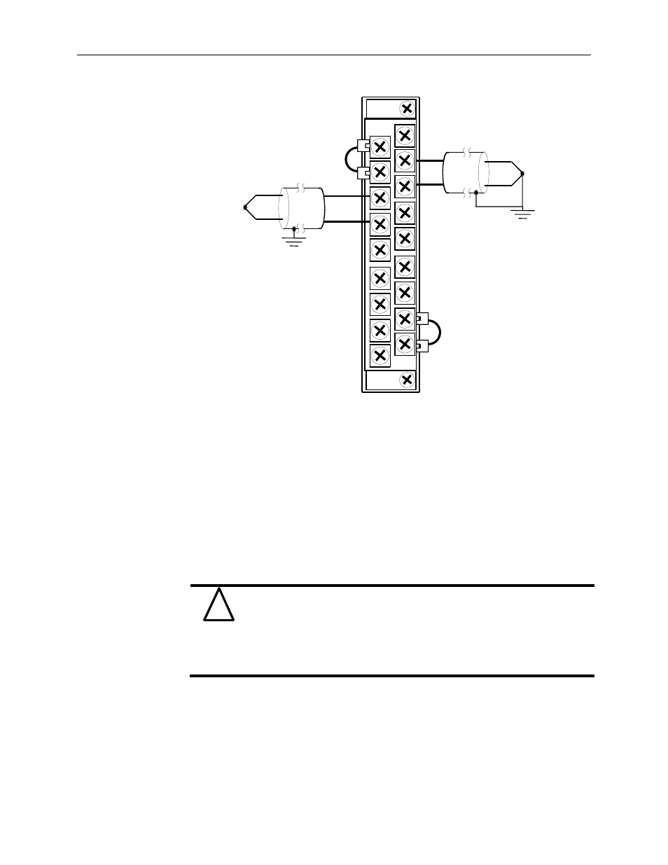
Note: When using an ungrounded thermocouple, the shield must be connected to
ground at the module end.
Section 3.8
Cold Junction
Compensation
To obtain accurate readings from each of the channels, the cold junction temperature
(temperature at the module’s terminal junction between the thermocouple wire and the
input channel) must be compensated for. Two cold junction compensating thermistors
have been integrated in the removable terminal block. These thermistors must remain
installed to retain accuracy.
Do not remove or loosen the cold junction compensating thermistor
assemblies located on between the two upper and lower CJC terminals.
Both thermistor assemblies are critical to ensure accurate thermocouple
input readings at each channel. The module will operate in the
thermocouple mode, but at reduced accuracy if either CJC sensor is
removed. See Determining Open-Circuit Response (Bits 6 and 5) on
page 4-6.
If either of the thermistor assemblies are accidentally removed, re-install them by
connecting each one across each pair of CJC terminals.
!
Attention
NC
IN0+
IN0-
IN1+
IN1-
IN2+
IN2-
CJC1-
CJC1+
Grounded Thermocouple
CJC0+
CJC0-
IN3+
IN3-
IN4+
IN4-
IN5+
IN5-
NC
Ungrounded Thermocouple
Figure 3-1 (Wiring Diagram)