1 configuration data file, 2 compact™ io isolated thermocouple module – Spectrum Controls 1769sc-IT6I User Manual
Page 36
4-2
Compact™ IO Isolated Thermocouple Module
User’s Manual Pub. 0300244-01 Rev. A
Note: Not all controllers support program access to the configuration file. Refer to
your controller’s user manual.
Section 4.2
Configuring
Channels
After module installation, you must configure operation details, such as thermocouple
type, temperature units, etc., for each channel. Channel configuration data for the module
is stored in the controller configuration file, which is both readable and writable.
The configuration data file is shown below. Bit definitions are provided in Channel
Configuration, below. Detailed definitions of each of the configuration parameters
follow the table.
4.2.1
Configuration Data File
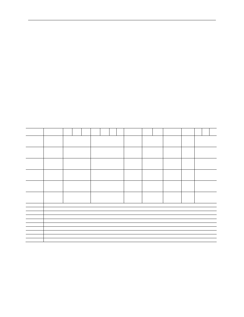
The default value of the configuration data is represented by zeros in the data file. The
structure of the channel configuration file is shown below.
Table 4-1 (Configuration Data File)
Word/
Bit
15
14 13 12 11 10 9 8
7
6 5
4
3 2 1 0
0
Disable
Channel 0
Data Format
Channel 0
Input Type
Channel 0
Temp Units
Channel 0
Open Circuit
Condition
Channel 0
Display
CJC
Channel 0
Not
Used
ADC Filter
Frequency
Channel 0
1
Disable
Channel 1
Data Format
Channel 1
Input Type
Channel 1
Temp Units
Channel 1
Open Circuit
Condition
Channel 1
Display
CJC
Channel 1
Not
Used
ADC Filter
Frequency
Channel 1
2
Disable
Channel 2
Data Format
Channel 2
Input Type
Channel 2
Temp Units
Channel 2
Open Circuit
Condition
Channel 2
Display
CJC
Channel 2
Not
Used
ADC Filter
Frequency
Channel 2
3
Disable
Channel 3
Data Format
Channel 3
Input Type
Channel 3
Temp Units
Channel 3
Open Circuit
Condition
Channel 3
Display
CJC
Channel 3
Not
Used
ADC Filter
Frequency
Channel 3
4
Disable
Channel 4
Data Format
Channel 4
Input Type
Channel 4
Temp Units
Channel 4
Open Circuit
Condition
Channel 4
Display
CJC
Channel 4
Not
Used
ADC Filter
Frequency
Channel 4
5
Disable
Channel 5
Data Format
Channel 5
Input Type
Channel 5
Temp Units
Channel 5
Open Circuit
Condition
Channel 5
Display
CJC
Channel 5
Not
Used
ADC Filter
Frequency
Channel 5
6 Not
Used
7 Not
Used
8 Not
Used
9 Not
Used
10 Not
Used
11 Not
Used
12 Not
Used
13 Not
Used
14 Not
Used
15 Not
Used
The configuration file can also be modified through the control program, if supported by
the controller. For information on configuring the module using RSLogix 500 (with
MicroLogix 1500 controller), see Appendix C; for RSLogix 5000 (CompactLogix
controller), see Appendix D; for RSNetworx (1769-ADN), see Appendix E. The
structure and bit settings are shown in the section below.