Spectrum Controls 1769sc-IT6I User Manual
Page 11
Chapter 1: Module Overview
1-3
User’s Manual Pub. 0300244-01 Rev. A
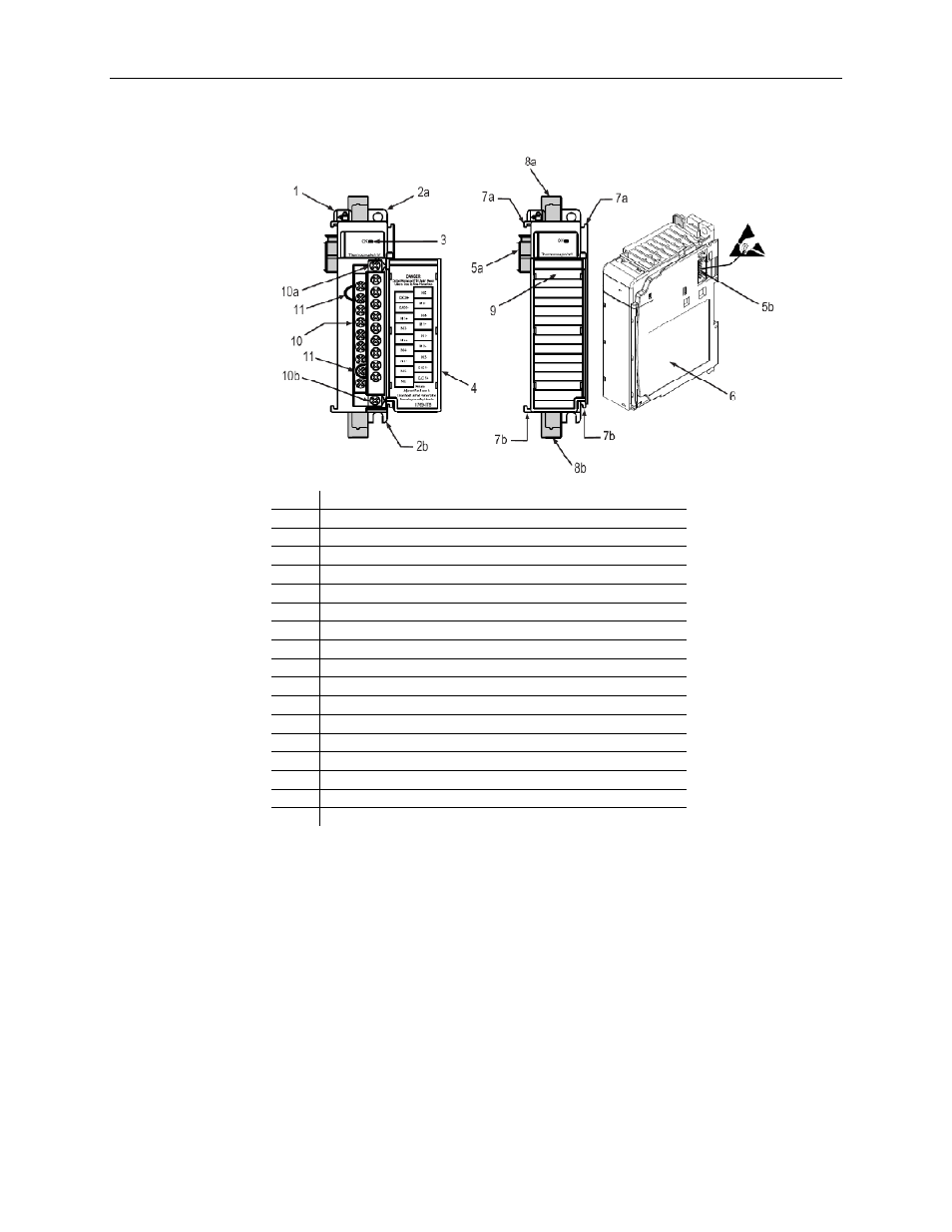
The illustration below shows the module’s hardware features.
Item Description
1 Bus
lever
2a
Upper panel mounting tab
2b
Lower panel mounting tab
3 Module
status
LED
4
Module door with terminal identification label
5a
Movable bus connector (bus interface) with female pins
5b
Stationary bus connector (bus interface) with male pins
6 Nameplate
label
7a
Upper tongue-and-groove slots
7b
Lower tongue-and-groove slots
8a
Upper DIN rail latch
8b
Lower DIN rail latch
9
Write-on label for user identification tags
10
Removable terminal block (RTB) with finger-safe cover
10a
RTB upper retaining screw
10b
RTB lower retaining screw
11 CJC
sensors
1.1.5
General Diagnostic Features
The module contains a diagnostic LED that helps you identify the source of problems that
may occur during power-up or during normal channel operation. The LED indicates both
status and power. Power-up and channel diagnostics are explained in Chapter 5,
Diagnostics and Troubleshooting.
Section 1.2
System Overview
The modules communicate to the controller through the bus interface. The modules also
receive 5 and 24V dc power through the bus interface.