Spectrum Controls 1769sc-IT6I User Manual
Page 35
User’s Manual Pub. 0300244-01 Rev. A
Chapter 4
Module Data, Status, and
Channel Configuration
After installing the 1769sc-IT6I Isolated Thermocouple/mV Input Module, you must
configure it for operation, usually using the programming software compatible with the
controller (for example, RSLogix 500 or RSLogix 5000). Once configuration is complete
and reflected in the ladder logic, you need to operate the module and verify its
configuration.
This chapter contains information on the following:
•
Module memory map
•
Configuring channels
•
Accessing input image file data
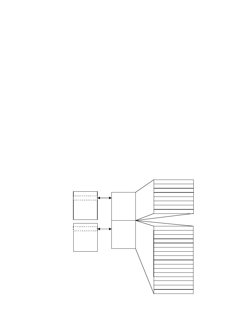
Section 4.1
Module
Memory Map
The module uses eight input words for data and status bits (input image), and seven
configuration
words.
Input Image
File
Input Image
8 words
Configuration
File
16 Words
Channel 0 Data Word
Channel 1 Data Word
Channel 2 Data Word
Channel 3 Data Word
Channel 4 Data Word
Channel 5 Data Word
General/Open-circuit Status
Bits
Over/Under Range Status Bits
Channel 0 Configuration Word
Channel 1 Configuration Word
Channel 2 Configuration Word
Channel 3 Configuration Word
Channel 4 Configuration Word
Channel 5 Configuration Word
Not Used
Not Used
Not Used
Not Used
Not Used
Not Used
Not Used
Memory Map
Word 0
Word 1
Word 2
Word 3
Word 4
Word 5
Word 6
Word 7
Word 0
Word 1
Word 2
Word 3
Word 4
Word 5
Word 6
Word 7
Word 8
Word 9
Word 10
Word 11
Word 12
Slot e
Configuration
File
Slot e
Not Used
Not Used
Not Used
Word 13
Word 14
Word 15