Spectrum Controls 1769sc-IT6I User Manual
Page 12
1-4
Compact™ IO Isolated Thermocouple Module
User’s Manual Pub. 0300244-01 Rev. A
1.2.1
System Operation
At power-up, the module performs a check of its internal circuits, memory, and basic
functions. During this time, the module status LED remains off. If no faults are found
during power-up diagnostics, the module status LED is turned on.
After power-up checks are complete, the module waits for valid channel configuration
data. If an invalid configuration is detected, the module generates a configuration error.
Once a channel is properly configured and enabled, it continuously converts the
thermocouple or millivolt input to a value within the range selected for that channel.
Each time a channel is read by the input module, that data value is tested by the module
for an over-range, under-range, open-circuit, or “input data not valid” condition. If such
a condition is detected, a unique bit is set in the channel status word. The channel status
word is described in Input Data File on page 4-10.
Using the module image table, the controller reads the two’s complement binary
converted thermocouple or millivolt data from the module. This typically occurs at the
end of the program scan or when commanded by the control program. If the controller
and the module determine that the data transfer has been made without error, the data is
used in the control program.
1.2.2
Module Operation
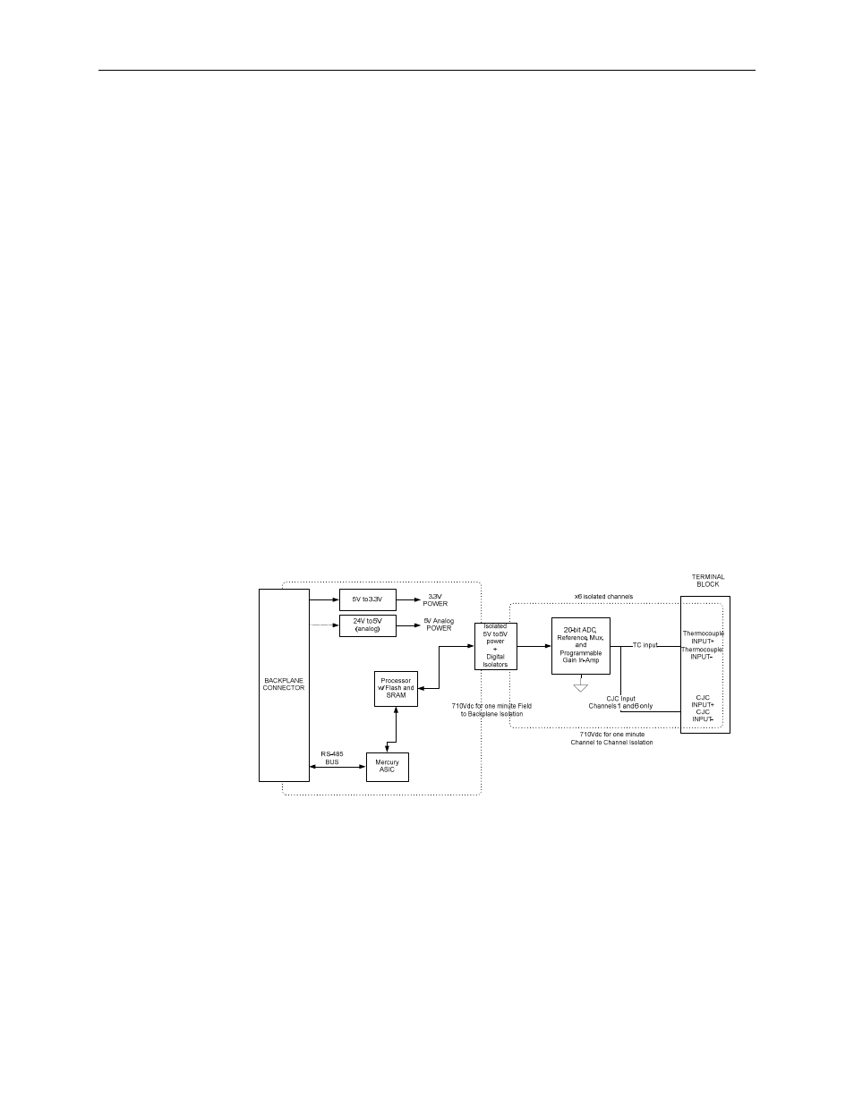
When the module receives a differential input from an analog device, the module’s
circuitry multiplexes the input into an A/D converter. The converter reads the signal and
converts it as required for the type of input. The module also continuously samples the
CJC sensors and compensates for temperature changes at the terminal block cold
junction, between the thermocouple wire and the input channel. See the block diagram
below.
Each channel can receive input signals from a thermocouple or millivolt analog input
device, depending upon how you configured the channel.
When configured for thermocouple input types, the module converts the analog input
voltages into cold-junction compensated and linearized digital temperature readings. The
module uses the National Institute of Standards and Technology (NIST) ITS-90 standard
for linearization for all thermocouple types (J, K, T, E, R, S, B, N, C, L).