Spectrum Controls 1769sc-IT6I User Manual
Page 44
4-10
Compact™ IO Isolated Thermocouple Module
User’s Manual Pub. 0300244-01 Rev. A
Section 4.4
Input
Data File
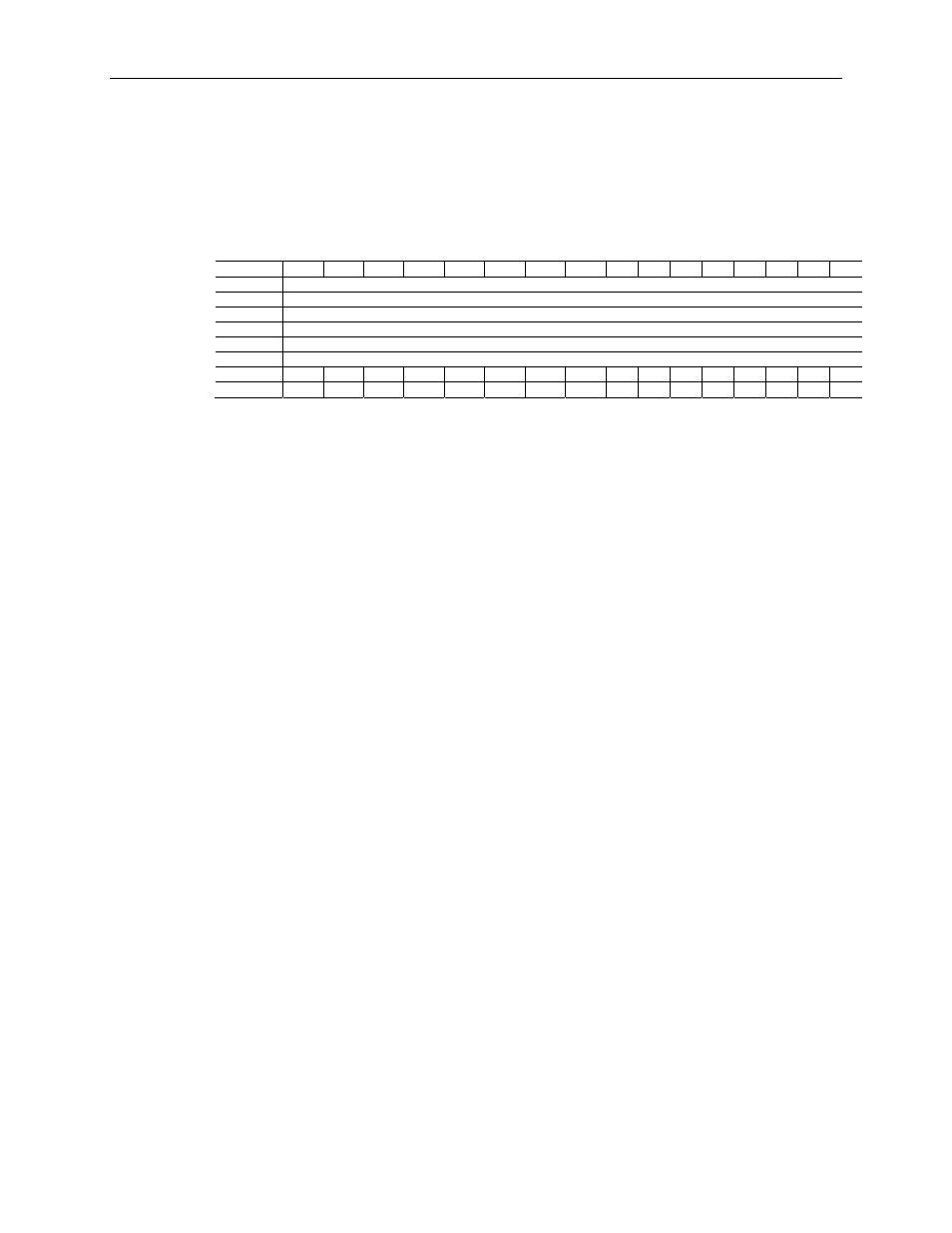
The input data table allows you to access module read data for use in the control
program, via word and bit access. The data table structure is shown in table below.
Table 4-7 (Input Data File)
Word/Bit 15 14 13 12 11 10 9 8 7 6 5 4 3 2 1 0
0
Analog Input Data Channel 0
1
Analog Input Data Channel 1
2
Analog Input Data Channel 2
3
Analog Input Data Channel 3
4
Analog Input Data Channel 4
5
Analog Input Data Channel 5
6
OC7 OC6 OC5 OC4 OC3 OC2 OC1 OC0 S7 S6 S5 S4 S3 S2 S1 S0
7
O7 O6 O5 O4 O3 O2 O1 O0 U7
U6
U5
U4
U3
U2
U1
U0
4.4.1
Input Data Values
Data words 0 through 5 correspond to channels 0 through 5 and contain the converted
analog input data from the input device. The most significant bit, bit 15, is the sign bit
(SGN).
4.4.2
General Status Bits (S0 to S7)
Bits S0 through S5 of word 6 contain the general status information for channels 0
through 5, respectively. Bits S6 and S7 contain general status information for the two
CJC sensors (S6 corresponds to CJC0, S7 to CJC1). If set (1), these bits indicate an error
(over- or under-range, open-circuit or input data not valid condition) associated with that
channel. The data not valid condition is described below.
Input Data Not Valid Condition
The general status bits S0 to S5 also indicate whether or not the input data for a particular
channel, 0 through 5, is being properly converted (valid) by the module. This “invalid
data” condition can occur (bit set) when the download of a new configuration to a
channel is accepted by the module (proper configuration) but before the A/D converter
can provide valid (properly configured) data to the 1769 bus master/controller. The
following information highlights the bit operation of the Data Not Valid condition.
1)
The default and module power-up bit condition is reset (0).
2)
The bit condition is set (1) when a new configuration is received and determined
valid by the module. The set (1) bit condition remains until the module begins
converting analog data for the previously accepted new configuration. When
conversion begins, the bit condition is reset (0). The amount of time it takes for
the module to begin the conversion process depends on the number of channels
being configured and the amount of configuration data downloaded by the
controller.
Note: If the new configuration is invalid, the bit function remains reset (0) and the
module posts a configuration error. See Configuration Errors on page 5-4.
3)
If A/D hardware errors prevent the conversion process from taking place, the bit
condition is set (1).