Spectrum Controls 1769sc-IT6I User Manual
Page 41
Chapter 4: Module, Data, Status, and Channel Configuration
4-7
User’s Manual Pub. 0300244-01 Rev. A
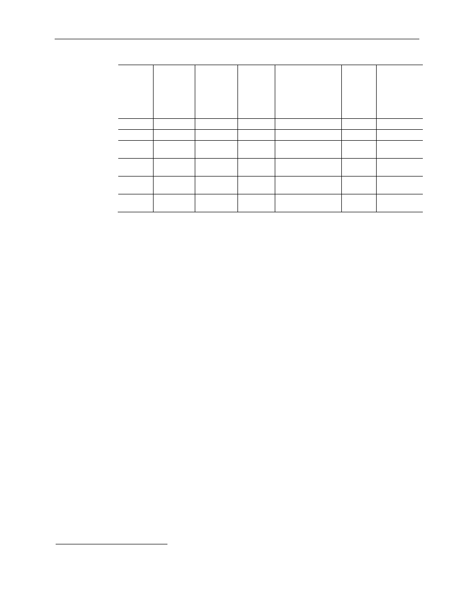
Table 4-6 (Filter Effects)
Input
Filter
Channel
Update
Time
(Ch 1 to 4)
Normal
Conversion
Mode
Channel
Update
Time
During CJC
Sample
(Ch 0 & 5)
7
Cut-Off
Frequency Repeatability
NMRR
50 Hz
Rejection
NMRR
60 Hz
Rejection
4.17 Hz
246 msec
500 msec
1 Hz
See Appendix A
74 dB
74 dB
10.0 Hz
106 msec
220 msec
2 Hz
See Appendix A
70 dB
70 dB
16.7 Hz
66 msec
140 msec
4 Hz
2x(4.17 Hz values)
From Appendix A
65 dB
NA
19.6 Hz
57 msec
122 msec
5 Hz
2x(4.17 Hz values)
From Appendix A
NA 74
dB
62 Hz
26 msec
52 msec
14 Hz
4x(4.17 Hz values
From Appendix A)
NA NA
470 Hz
8 msec
24 msec
109 Hz
10x(4.17 Hz values)
From Appendix A
NA NA
Effects of Filter Frequency on Noise Rejection
The filter frequency that you choose for a module channel determines the amount of
noise rejection for the inputs. A lower frequency (4.17 Hz versus 470 Hz) provides better
noise rejection and improves repeatability, but also increases channel update time. A
higher filter frequency provides lower noise rejection, but decreases the channel update
time and negatively affects repeatability.
When selecting a filter frequency, be sure to consider the cut-off frequency to obtain
acceptable noise rejection. Choose a filter frequency so that your fastest-changing signal
is below that of the filter’s cut-off frequency.
Table 4-6 above lists the expected normal mode rejection for each of the filter settings.
Note: Transducer power supply noise, transducer circuit noise, or process variable
irregularities may also be sources of normal mode noise.
Cut-Off Frequency
The filter cut-off frequency, -3 dB, is the point on the frequency response curve where
frequency components of the input signal are passed with 3 dB of attenuation. Table 4-6
shows cut-off frequencies for the supported filters.
All input frequency components at or below the cut-off frequency are passed by the
digital filter with less than 3 dB of attenuation. All frequency components above the cut-
off frequency are increasingly attenuated.
The cut-off frequency for each channel is defined by its filter frequency selection.
Choose a filter frequency so that your fastest changing signal is below that of the filter’s
cut-off frequency. The cut-off frequency should not be confused with the update time.
The cut-off frequency relates to how the digital filter attenuates frequency components of
the input signal. The update time defines the rate at which an input channel is scanned
and its channel data word is updated.
7
Use channel update rates for channels 1 through 4 when CJCs are not being sampled.