Spectrum Controls 1769sc-HART Modules User Manual
Page 107
Chapter 7: Enabling and Using HART on the 1769sc-OF4IH
User’s Manual 0300217-03 Rev. A
7-41
Section 7.5
HART Protocol
Overview
In order to read and write HART commands to and from the field device reliably using
the OF4IH, you must have a basic knowledge of the HART protocol. This section will
explain in detail the various pieces that make up the HART message and how to
formulate the message and send it to the field device using the module specific Pass-
Through command, which was described earlier in this chapter.
7.5.1 Message Format
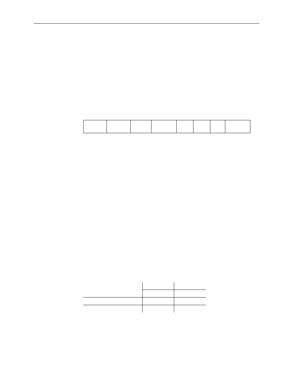
HART protocol specifies a message structure as follows:
Figure 7-11 (HART Message Structure)
Preamble Start
Character
Address Command Byte
Count
Status Data Checksum
Note: The HART protocol supports two different formats, long and short frame. Older
HART instruments (up to HART revision 4) used a short frame format. In this format,
the address of the slave device is either 0, for non-multidrop devices using the 4-20mA
current signal, or 1-15 for multidrop devices.
HART revision 5 introduced the long frame format. In this format, the address of a slave
device is a worldwide, unique 38-bit number derived from the manufacturer code, the
device type code, and the device identification number. The long frame format provides
extra security against acceptance of commands meant for other devices, due to external
interference or excessive crosstalk. The OF4IH supports only the long frame format.
Each item of the message structure shown above is explained as follows.
Preamble
The preamble consists of three or more hexadecimal FF characters (all 1s) allowing the
receiving modem to get its frequency-detection circuits synchronized to the signal after
any pause in transmission.
Note: The preamble does not need to be included in the HART message when using
the module specific Pass-through command. The Pass-through command already
includes the preamble.
Start Character
The start character in a HART message has various values, indicating which frame
format is being used, the source of the message, and whether a field device is in burst
mode. The possible definitions are shown in the table below.
Table 7-17 (Start Character Definition)
Short Frame Long Frame
Master to slave
02 (Hex)
82 (Hex)
Slave to master
06 (Hex)
86 (Hex)
Burst mode from slave
01 (Hex)
81 (Hex)
Address
The address field contains both the host and field device addresses for the message.
These may be contained in a single byte (short frame format) or in five bytes (long frame
format). Since the module presently only supports the long frame form, we will omit the