Remote cable connection – SOR Single Point Ultrasonic Level Switch User Manual
Page 3
Form 841 (08.13) ©SOR Inc.
3/16
Remote Cable Connection
Bracket
Open Sump or Basin
Do not suspend the unit by rigid conduit
installed in the electrical hub. When installing
the unit over an open sump or basin, use a
suitable bracket to support the instrument.
NOTE: The instrument must be positioned so that
overfl ow does not fl ood electrical housing. (See
)
Conduit must be installed
between the sensor base
and the electronics housing
to provide a raceway for
sensor extension cables.
(See
) The sensor base
and the electronics hous-
ing are suitable for use in
Class I Group C & D; Class
II Groups E, F & G; Division
1 & 2 Hazardous Locations.
All conduit and fittings used
for the installation must
equal or exceed this rating to
maintain the explosion proof
integrity of the assembly.
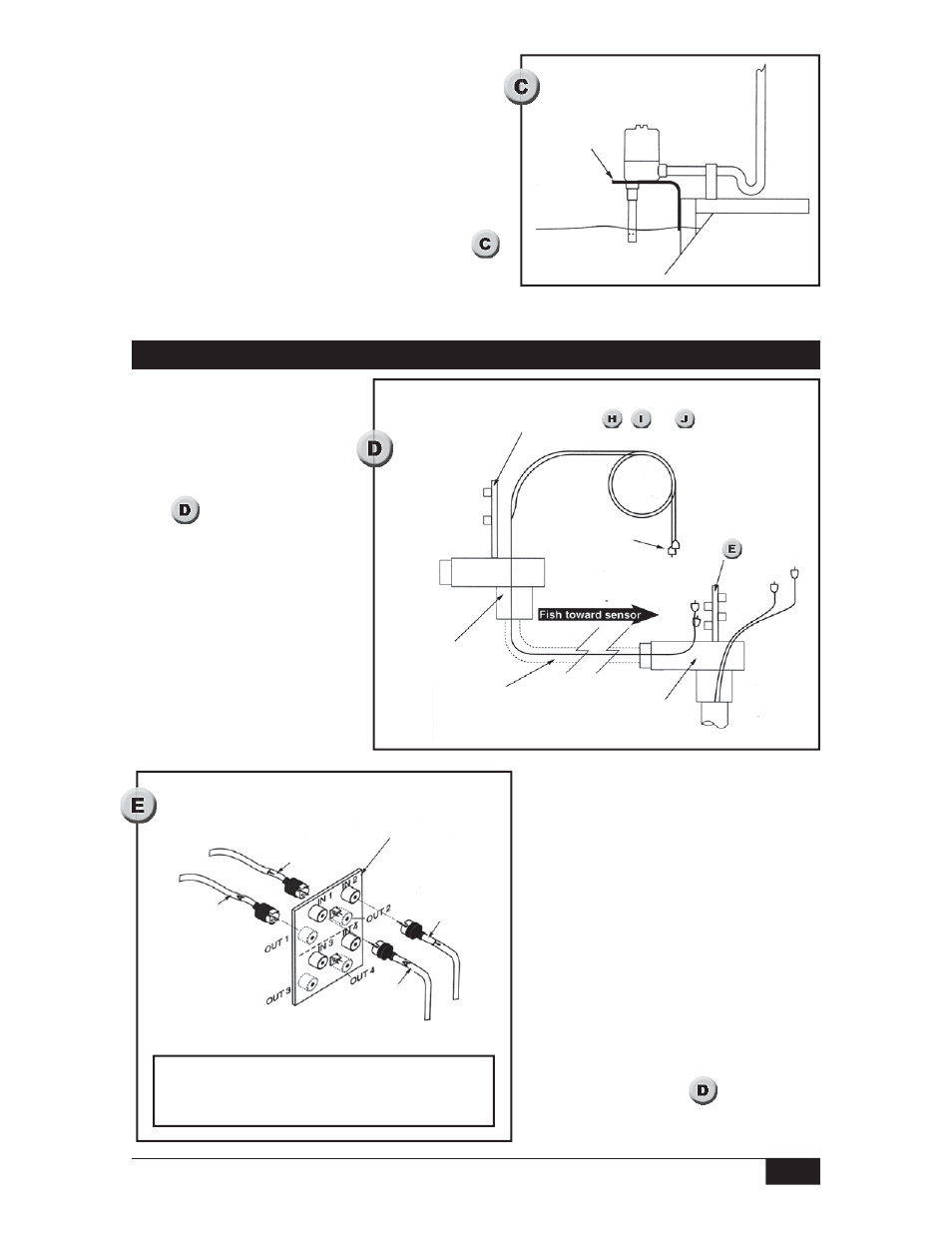
Fishing the sensor
extension cables
Two sensor extension cables
are supplied. Both ends of the
cables are terminated and labeled
at the factory. Use care to avoid
damaging the factory installed
coax connectors while fishing the
sensor extension cables through
the conduit. Pull cables from the
electronics housing so that the
free ends follow the fish through
the conduit. (See
)
Control Board
See Figures
,
, &
Remote
Interconnect
Board
See
Conduit must meet
Class I Group C & D; Class II
Groups E, F & G; Div 1 & 2
Sensor Base
Electronics
Housing
Protect factory
installed plugs
Connect Extension
Lead T to
OUT 2
Connect
Extension
Lead A to
OUT 1
Remote Interconnect
Board located inside
sensor base
Connect Sensor
Lead (T)
to IN 2
Connect
Sensor Lead
(A) to IN 1
OUT connections are located on the opposite side
of the board from the IN connections. Do not use
positions 3 and 4 to connect wires.