SOR Single Point RF Level Switch User Manual
Page 7
Form 830 (03.13) ©SOR Inc.
7/12
Disconnect power to the unit.
Remove the housing cover.
Remove two mounting screws and slide out PC board to expose green ground screw
in the bottom of the housing.
Remove the ground screw and ring terminal from inside the housing.
Disconnect the banana plug from the sensor.
Connect the banana plug from the new board to the sensor. Make sure the connection
is tight.
Slide the ring terminal onto the ground screw. Replace the ground screw in the bottom
of the housing.
Slide the PC board into the grooves in the plastic ring inside the housing.
Replace the two mounting screws into the plastic ring. These screws are self-tapping.
Do not overtighten.
Circuit Board Replacement
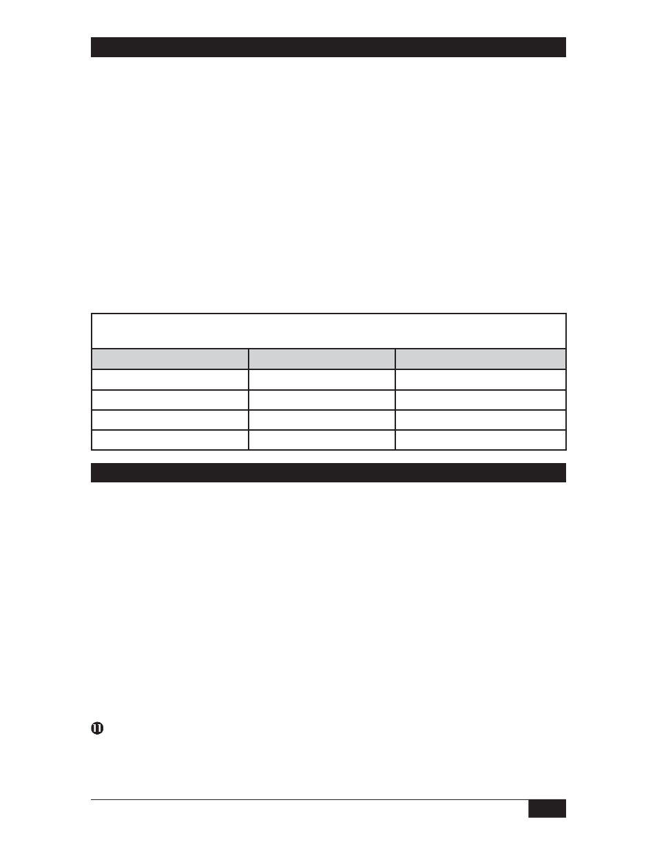
Replacement Circuit Boards can only be ordered from SOR. Match the first five characters of your
model number with those shown below to select the proper replacement board part number.
SOR Model Number
Power Supply
Circuit Board Part Number
651K5
12 VDC
99-401
651K6
24 VDC
99-376
651K7
12- VAC
99-377
651KB
240 VAC
99-378
Sensor Replacement
Disconnect power to the unit.
Remove the housing cover.
Remove two mounting screws and slide out the PC board to expose the sensor
connection in the bottom of the housing.
Disconnect the banana plug from the sensor.
Unscrew the sensor from the housing.
Apply thread sealant such as Teflon tape to the male threads of the new sensor.
Thread the new sensor into the bottom of the housing.
Connect the banana plug into the new sensor. Make sure the connection is tight.
Slide the PC board into the grooves in the plastic ring inside the housing.
Replace the two mounting screws into the plastic ring. These screws are self-tapping.
Do not overtighten.
Replace the housing cover.
Replacement Sensors
See Form 1100 RF Catalog for replacement sensor model numbers.
NOTE: Replacement of circuit boards not
allowed on agency listed units.