SOR Single Point RF Level Switch User Manual
Page 2
2/12
Form 830 (03.13) ©SOR Inc.
Turn sensitivity adjustment clockwise (25 turns) to increase sensitivity until the LED
illuminates indicating that the relay is energized. The unit is normally shipped in the
most sensitive position.
The fail-safe mode selector switch JP1 is normally shipped in the lower position when
the instrument is oriented with the sensor pointing downward (6 o’clock). When the
instrument is powered up, the relay is de-energized (LED goes out) when no process
material is on the sensor.
Turn sensitivity adjustment counterclockwise to decrease sensitivity until the LED goes
out. This normally occurs within 2-1/2 to 3-1/2 turns from the full increase position.
Turn the sensitivity adjustment slowly clockwise, then counterclockwise, 1/2 to 1 turn
to check the null position for verification that the bridge is balanced. It is desirable to
closely bracket the position where the LED went out.
Turn the sensitivity adjustment one turn counterclocwise from the null position. Next,
slowly move a hand toward the probe to touch it. The LED should stay out until the
probe is touched. Should it illuminate when in close proximity, turn sensitivity control
counterclockwise so the LED stays out until a hand touches the probe.
Usually, 1-2 turns will locate the new null point.
It is desirable to simulate the actual application conditions so the device can be more
precisely bench tested/calibrated, ensuring better on-line performance.
When practical, use a small container of actual process material. If the actual process
vessel is metal, use a metal container (coffee can, etc.) and ground it to the instrument
housing. If the actual process vessel is an insulator, such as fiberglass, use a plastic
container.
Immerse the sensor in the process material; the LED should illuminate. If not, it may be
necessary to increase sensitivity.
To detect an interface, such as oil/water or foam/liquid, the lighter material must be
on the sensor, then tuned out. Then adjust the sensitivity to detect the heavier process
material. (See
and
)
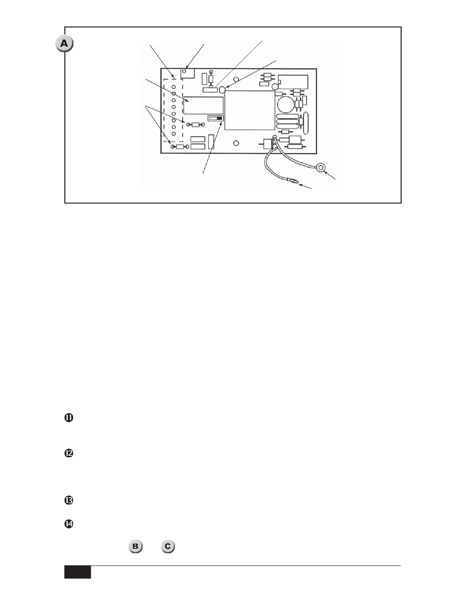
Sensitivity
Adjustment
LED
Equipment Case
Ground Connector
Banana Plug to Sensor Jack
Top View
JP1 Fail Safe Selector Switch
Line Fuses
K1 Output Relay
Screw Clamp Terminal Block
Timer Module (optional)