SOR Single Point RF Level Switch User Manual
Page 3
Form 830 (03.13) ©SOR Inc.
3/12
Installation
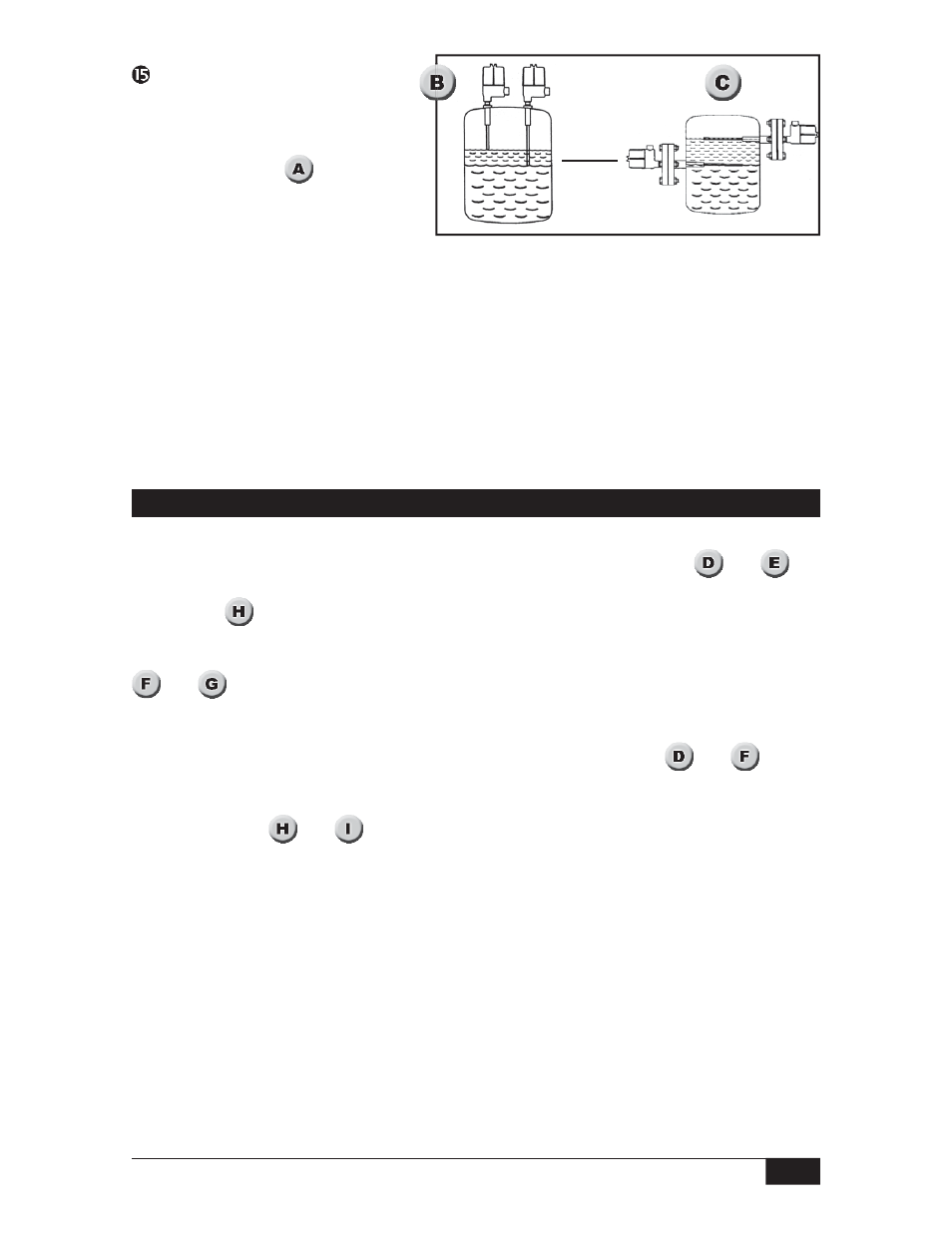
Oil
Water
Standard confi guration is a 3/4” NPT(M) pipe nipple that threads into a 3/4” NPT(F) ves-
sel nozzle of half coupling. Allow a 4-inch turn radius for the housing. (See
and
)
)
Sometimes open tanks, vats, sumps or basins require a locally made bracket mount similar
to shown in
p
p
.
Optional confi guration is a raised face ANSI flange. See catalog 1100 for selection. (See
p
p
p
and
)
Orientation. The control can be mounted in any position. Sensitivity is optimized when the
greatest surface area of the sensor is parallel to the process level. (See
p
and
)
When the process is adhesive, i.e. it tends to coat the sensor, it may be desirable to mount
the unit on a 45
o
angle to reduce product build-up and to increase its effective
surface area. (See
g
g
g
and
)
Placement and orientation of the sensor in a vessel is frequently determined by available
nozzles. The sensor should be away from fill points to avoid false trips. The insulator
bushing on the sensor should protrude a minimum of 1” from the inner wall of the vessel.
The sensor must not touch any metal, nor should conductive product build-up be allowed
to bridge between the sensor and a grounded metal tank wall.
If the sensor is a solid rod it may be cut or bent for clearance or placement. Use a 3-inch
radius if a bend is required. It is permissible to increase sensor length by welding a length
of identical rod to the supplied sensor. If the sensor is flexible cable, do not cut or modify it
in any way, as sensor integrity will be compromised.
Time Delay: The Series 650
has a built-in 0.5 second delay
to energize the output relay.
An adjustable delay feature
is optional. (See
y
y
y
, Timer
Module.)
0.5 delay ON up to 60 seconds OFF
0.5 delay OFF up to 60 seconds ON
The optional time delay is a 12-turn pot; full CCW is 0.5 sec, full CW is 60 sec. When the
timer board is unplugged, delay is 0.5 sec. This option may be used to increase the dead
band at set point, compensate for wave effects or turbulence and free fall time in solids.
NOTE: Use delay ON with JP1 fail-safe in upper position.
Use delay OFF with JP1 fail-safe in lower position. (Opposite position of JP1 will reverse
operation.)