SOR 815PT Smart Pressure Transmitter User Manual
Page 7
Form 1571 (10.13) ©SOR Inc.
7/24
R
L
> 250
The table below contains a short description of the four 815PT device variables.
Device Definition Table
Variables
Value
Default Unit
Primary Variable (PV)
Pressure
PSI
Secondary Variable (SV)
Temperature
Degrees Celcius
Tertiary Variable (TV)
Loop voltage
Volts
Feduciary Variable (FV)
Dynamic
n/a
Under normal operating conditions, the analog output signal of the 815PT will remain
between 4mA and 20mA. In the event that the pressure goes beyond the normal
operating range of the device or in a fault condition, the 815PT will indicate the
condition on the 4-20 mA loop. The table below summarizes the 815PT loop current
with the associated fault indication.
Fault Current Indication
Loop Current
Description
3.6 mA
Fault Indication (Configurable: 3.6 mA or 21.0 mA)
3.8 mA
Low limit of output range
20.5 mA
High limit of output range
21.0 mA
Fault Indication (Configurable: 3.6 mA or 21.0 mA)
Device Variables and Fault Current Indicators
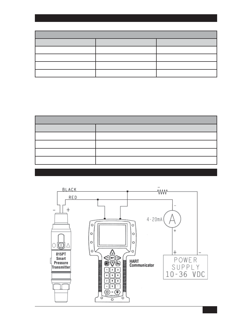
Confi guration with HART Communicator
4-20 mA Output
- Adjustable Dead Band Explosion Proof Pressure Switch (4 pages)
- 805QS Pressure Switch-Transmitter (8 pages)
- 805PT Pressure Transmitter (12 pages)
- Big Hermet Explosion Proof, Hermetically Sealed, Pressure Switch (8 pages)
- Bourdon Tube Explosion Proof Pressure Switch (4 pages)
- Dual Hi-Lo Explosion Proof Sealed Pressure Switch (4 pages)
- Explosion Proof (8 pages)
- Explosion Proof (4 pages)
- Explosion Proof Pressure Switch UL/CSA/ATEX (8 pages)
- Mini-Hermet (8 pages)
- Mini-Hermet (4 pages)
- Sub Mini Hermet (4 pages)
- Omni Weatherproof Pressure Switch (4 pages)
- Weatherproof Pressure Switch (4 pages)
- Weatherproof Pressure Switch (2 pages)
- 805PT Pressure Transmitter (8 pages)
- 815DT Smart (24 pages)
- 534CR Pressure Transmitter (8 pages)
- 534HS Two-Wire Pressure Transmitters (12 pages)
- 536CR Low Power Pressure Transmitters (8 pages)
- 536HS Low Power Pressure Transmitters (8 pages)
- 510IM Immersible Transmitter (4 pages)
- 503FR Fixed Range Pressure Transmitter (4 pages)
- 101/121 Differential Pressure Switches (12 pages)
- Dual Opposed Diaphragm (12 pages)
- High Static Operation (8 pages)
- High Static Operation (12 pages)
- Low Pressure Switch Low Range Series 20 (8 pages)
- Low Range (4 pages)
- Single Diaphragm (4 pages)
- Big Hermet (12 pages)
- Direct or Remote Mount Explosion Proof UL/CSA/ATEX (8 pages)
- Side Mounted Level Switches (16 pages)
- Flanged Level Switches (4 pages)
- Sealed Level Switches (8 pages)
- 1510 Side Mounted Level Switch (8 pages)
- 1520 Electric Flow Switch (8 pages)
- 1530 Pneumatic Level Switch (4 pages)
- 1540 Side Mounted Non-Bleed Pneumatic Level Switch (4 pages)
- 1550 Top Mounted Level Switch (8 pages)
- 1710 Compact Level Switch (8 pages)
- Multi Point RF Level Switch (36 pages)
- Single Point RF Level Switch (12 pages)
- Single Point RF Level Switch (16 pages)