6 vacuum pump, 7 pressure control valve – Martin Christ Epsilon 2-4 LSCplus User Manual
Page 38
Freeze-dryer EPSILON 1-4 LSCplus
Freeze-dryer EPSILON 2-4 LSCplus
5 Set-up and connection
38
Version 04/2014, Rev. 1.4 of 09/12/2014 • sb
Translation of the original operating manual
Pos: 107 /20 0 Ch rist/3 61 G T-BA L abo r-Pilot (PROJEKTE)/Epsilo n 2 -4 LSC plus Sta nda rd/0 50 Auf stellu ng u nd Ansc hluss/ 050 -00 60 Vak uu mpu mpe E 1-4 _2- 4 @ 2 5\m od_ 140 498 473 6896 _68 .docx @ 1 860 71 @ 2 @ 1
5.4.6
Vakuum pum pe
5.6 Vacuum pump
NOTE
Please refer to the separate operating manual of the vacuum pump and
the exhaust filter!
The vacuum pump must be connected to the vacuum connector of the unit
and its plug must be plugged into the IEC C14 connector on the back of the
unit (see chapter 2.1.1 - "Functional and operating elements").
The oil mist that escapes when the pump is in operation must be retained
or carried off by way of an oil mist separator.
• We strongly recommend using an oil mist separator. This filter prevents
air pollution by oil mist.
• In order to carry off the oil mist, connect a suitable hose to the exhaust
port of the vacuum pump (RZ-2.5 and RC-6: ½", DUO 5 or DUO 10 ¾").
• The hose must be laid so that the condensate cannot flow back into the
pump. In the case of upward leading hoses, we recommend using a
separator (Woulfe's bottle or wash bottle).
Pos: 108 /01 0 Univ ersal mod ule/L eerz eile @ 0\m od_ 120 211 624 450 0_0. docx @ 11 4 @ @ 1
Pos: 109 /20 0 Ch rist/3 61 G T-BA L abo r-Pilot (PROJEKTE)/Epsilo n 2 -4 LSC plus Sta nda rd/0 50 Auf stellu ng u nd Ansc hluss/ 050 -00 70 D ruckst eue rven til E1-4 _2- 4 @ 25\ mod _140 498 473 780 6_6 8.doc x @ 1 860 85 @ 2 @ 1
5.7 Pressure control valve
The pressure control valve is integrated in the suction pipe between the
vacuum pump and ice condenser chamber. During certain, specified
process phases, it interrupts the volume flow to the vacuum pump (see
chapter 2.2.1 - "General information on freeze-drying").
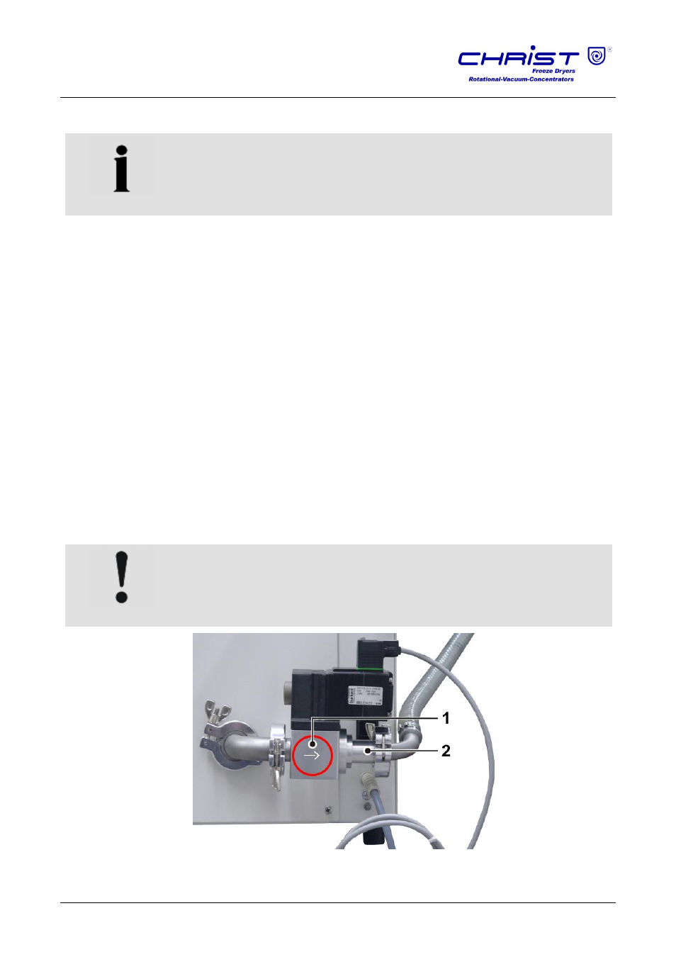
CAUTION
Observe the installation direction of the pressure control valve!
1
Pressure control valve
2 Vacuum pump
connection
Fig. 18: Installation of the pressure control valve
Pos: 110 /01 0 Univ ersal mod ule/Seit enwec hsel @ 0\m od_ 120 211 624 4312 _0. docx @ 10 5 @ @ 1