LINK Systems OmniLink - PLC Interface User Manual
Page 20
June 5, 2000
Man ual Rev 1 .0
3.6
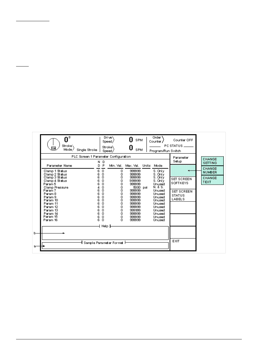
Figure 3.5:
Example Parameter Configuration Screen
Status Message
Each message can be up to 15 characters long. This is the message that will be
displayed on the screen when the PLC selects this message number. To change a
message description, place the editing cursor in the message to be changed and
press the “CHANGE TEXT” softkey. Enter the new message using the text entry
system described in Section 2.
Color
Each message can be one of 4 color combinations - “Normal” (black text on a
white background), “Green” (black text on a green background), “Yellow” (black
text on a yellow background), and “Red” (white text on a red background). To
change a message color, place the editing cursor on the color of the message to
change and press the “CHANGE SETTING” softkey. Select the color desired
from the list that appears and hit the “ENT” key. A small block to the right of the
color name will be displayed in the color selected.
There are 64 possible parameter status messages. Use the “PREVIOUS PAGE” softkey to display the
previous group of messages. Likewise, use the “NEXT PAGE” softkey to see the next group of
messages.
Section 3.4
Parameter Configuration
Up to 16 user defined parameters can be displayed on each of 4 PLC screens. These parameters must be
named and configured before use. Figure 3.5 shows an example parameter configuration screen.