Pinout assignments 76, Appendix, Ba d c – Hatteland Display HT C02HI (Compact Entry Level) User Manual
Page 76
Pinout Assignments
76
IND100241-18
Appendix
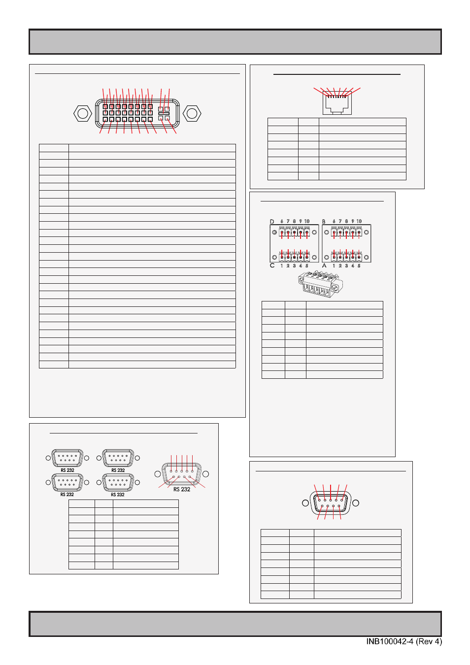
18/24/24+5 pin DVI-D, DVI-I, Single Link, Dual Link Combined Female
1 2 3 4 5 6 7 8 C1 C2
9 10 11 12 13 14 15 16 C5
17 18 19 20 21 22 23 24 C3 C4
PIN 01 T.M.D.S. Data2 - (Digital - RED link 1)
PIN 02 T.M.D.S. Data2 + (Digital + RED link 1)
PIN 03 T.M.D.S. Data2/4 Shield
PIN 04 T.M.D.S. Data4 - (Digital - GREEN link 2)
PIN 05 T.M.D.S. Data4 + (Digital + GREEN link 2)
PIN 06 DDC Clock
PIN 07 DDC Data
PIN 08 Analog Vertical Sync (DVI-I only)
PIN 09 T.M.D.S. Data1 - (Digital - GREEN link 1)
PIN 10 T.M.D.S. Data1 + (Digital + GREEN link 1)
PIN 11 T.M.D.S. Data1/3 Shield
PIN 12 T.M.D.S. Data3 - (Digital - BLUE link 2)
PIN 13 T.M.D.S. Data3 + (Digital + BLUE link 2)
PIN 14 +5V Power (for standby mode)
PIN 15 Ground (for +5V and analog sync)
PIN 16 Hot Plug Detect
PIN 17 T.M.D.S. Data0 - (Digital - BLUE link 1) and digital sync.
PIN 18 T.M.D.S. Data0 + (Digital + BLUE link 1) and digital sync.
PIN 19 T.M.D.S. Data0/5 Shield
PIN 20 T.M.D.S. Data5 - (Digital - RED link 2)
PIN 21 T.M.D.S. Data5 + (Digital - RED link 2)
PIN 22 T.M.D.S. Clock Shield
PIN 23 T.M.D.S. Clock + (Digital clock + (Links 1 and 2)
PIN 24 T.M.D.S. Clock - (Digital clock - (Links 1 and 2)
PIN C1 Analog RED
PIN C2 Analog GREEN
PIN C3 Analog BLUE
PIN C4 Analog Horizontal Sync.
PIN C5 Analog Ground (return for RGB signals)
DDC = Display Data Channel.
.M.D.S = Transition Minimized Differential Signal
PIN C1,C2,C3,C4 = Only present on DVI-I connectors.
NOTE: Connector shows a DUAL LINK design, but some units may not support it.
Only units with 1920x1200 or more in resolution require / support DUAL LINK.
8-pin RJ45 10/100/1000Mbps LAN/Ethernet
1 2 3 4 5 6 7 8
PIN 01 D0P+ Differential Pair 0 (Positive)
PIN 02 D0N- Differential Pair 0 (Negative)
PIN 03 D1P+ Differential Pair 1 (Positive)
PIN 04 D2P+ Differential Pair 2 (Positive)
PIN 05 D2N- Differential Pair 2 (Negative)
PIN 06 D1N- Differential Pair 1 (Negative)
PIN 07 D3P+ Differential Pair 3 (Positive)
PIN 08 D3N- Differential Pair 3 (Negative)
10+10 pin RS-422 / RS-485 NMEA Module
Type Number “PCA100293-1”
6 7 8 9 10
1 2 3 4 5
6 7 8 9 10
1 2 3 4 5
PIN 01 TxD- Transmit Data Negative
PIN 02 TxD+ Transmit Data Positive
PIN 03 GND Isolated Ground
PIN 04 RxD- Receive Data Negative
PIN 05 RxD+ Receive Data Positive
PIN 06 TxD- Transmit Data Negative
PIN 07 TxD+ Transmit Data Positive
PIN 08 GND Isolated Ground
PIN 09 RxD- Receive Data Negative
PIN 10 RxD+ Receive Data Positive
RS-485 Half Duplex (2-wire) Confi guration:
Connect TX and RX pair-wise:
TX- to RX-, TX+ to RX+.
*Note: The jumper for “force of transmitter” is
open by factory default. For some custom
models this jumper is preset to closed (active),
in that case unit has to be opened and jumper
set to open to allow Half Duplex mode.
COM Module RS-232 - 4 x ports, 9-pin DSUB Male
Type Number “PCA100294-1”
B
A
D
C
1 2 3 4 5
6 7
8 9
PIN 01 DCD Data Carrier Detect
PIN 02 RxD Receive Data
PIN 03 TxD Transmit Data
PIN 04 DTR Data Terminal Ready
PIN 05 GND Signal Ground
PIN 06 DSR Data Set Ready
PIN 07 RTS Request To Send
PIN 08 CTS Clear To Send
PIN 09 RI
Ring Indicator
Serial COM RS-232 non-isolated, 9-pin DSUB Male
1 2 3 4 5
6 7 8 9
PIN 01 DCD
Data Carrier Detect
PIN 02 RxD
Receive Data
PIN 03 TxD
Transmit Data
PIN 04 DTR
Data Terminal Ready
PIN 05 GND
Signal Ground
PIN 06 DSR
Data Set Ready
PIN 07 RTS
Request To Send
PIN 08 CTS
Clear To Send
PIN 09 RI
Ring Indicator