Physical connections 31 – Hatteland Display HT C02HI (Compact Entry Level) User Manual
Page 31
Physical Connections
31
IND100133-56
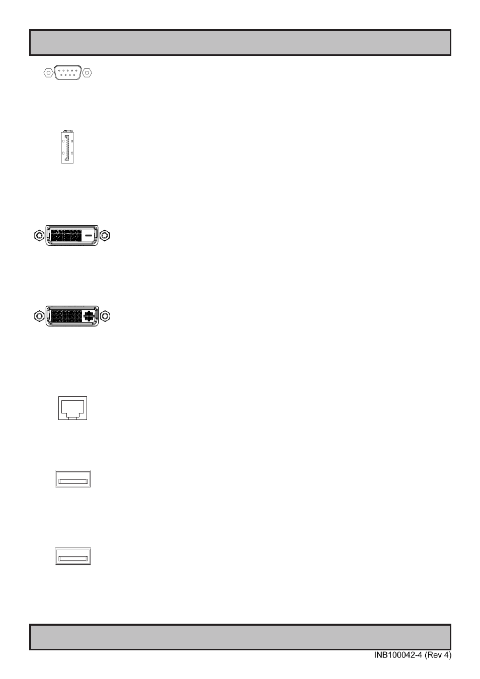
1+1 x COM Serial Port INPUT/OUTPUT:
Supports RS-232 (COM1) or RS-485/422 (COM2) using D-SUB 9P Male on-board connectors. Fasten the cable to the
connector using the provided screws on the cable housing itself. For configuration, please review the Appendix
chapter, section “BIOS - On-board COM Ports Configuration”.
1 x DisplayPort (DP) OUTPUT:
Connect your DP (male) cable to the DisplayPort (v1.2) 20P connector (female) on the rear side of the unit. The DP
has its own locking mechanism that locks the plug inserted. Make sure the plug “clicks” into place to verify a proper
and secure connection.
Note: Signal Output will be disabled if additional graphics card is installed and present in one of the PCI/PCIe slots!
1 x DVI-D OUTPUT:
Connect your DVI cable to the DVI-D 24P connectors (female) on the rear side of the unit. If possible, screw the DVI
cable to the connector and make sure you don’t bend any of the pins inside the DVI cable connector.
Note: Signal Output will be disabled if additional graphics card is installed and present in one of the PCI/PCIe slots!
1x DVI-I OUTPUT:
Connect your DVI cable to the DVI-I 29P connector (female) on the rear side of the unit. If possible, screw the DVI
cables to the connector and make sure you don’t bend any of the pins inside the DVI cable connector.
Note: Signal Output will be disabled if additional graphics card is installed and present in one of the PCI/PCIe slots!
The DVI-I OUT connector can be configured as RGB OUT (High Density D-SUB 15P) with the provided adapter in
contents of package.
4 x Network INPUT/OUTPUT:
Supports 10/100/1000Mbps Ethernet (LAN) through either 2 x Intel® or 2 x Realtek driver based. All 4 LAN connectors
can be used at the same time. Suitable for twisted pair cables CAT.5E. Make sure the network cable connector ”clicks”
into the RJ-45 connectors.
1 x USB1.1 and 1 x USB2.0 REAR INPUT/OUTPUT:
Supports USB1.1 (12Mbps, <10m) or USB1.1/2.0 (480Mbps, <5m) compliant peripherals. Drivers for most USB
devices are usually included in operating system or on separate installation CD’s delivered with Third Party products.
As indicated the lower port can be configured to operating in USB1.1 mode only via BIOS. The other port can support
USB1.1/2.0 depending on external equipment connected.
2 x USB3.0 REAR INPUT/OUTPUT:
Supports both USB1.1/2.0 compliant peripherals (backward compability mode) including the newer USB3.0 (5.0Gbps,
<3.0m) protocol for increased data bandwidth. Drivers for most USB devices are usually included in operating system
or on separate installation CD’s delivered with Third Party products. For most stable operation, only USB3.0 specific
external compliant peripherals should be connected to thes ports, as some USB1.1/2.0 devices may not be fully
compatible. Local testing of USB1.1/2.0 equipment connected to these ports should otherwise be performed.