Appendix pin assignments – Hatteland Display 20 inch - HM 20T07 CMD User Manual
Page 67
67
IND100241-7
Appendix
Pin Assignments
Note:
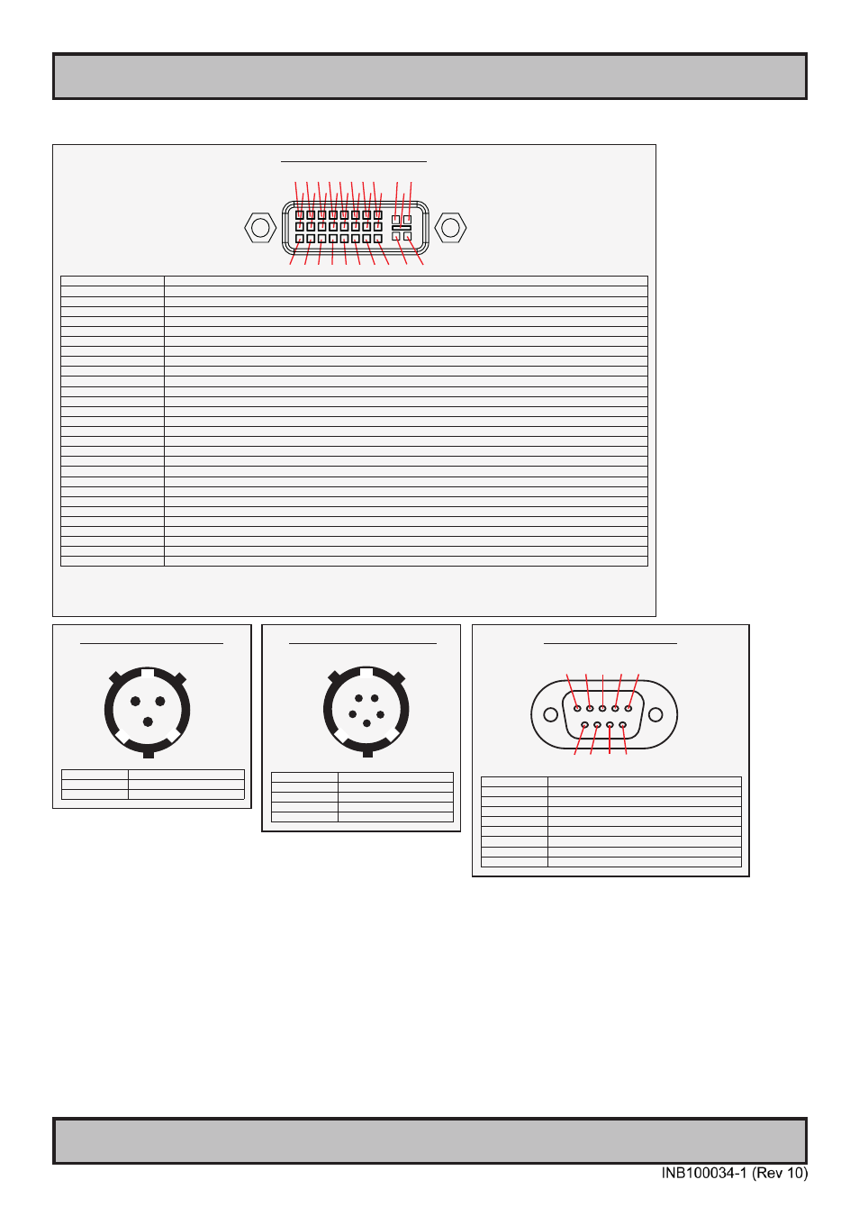
Connectors are seen from users Point Of View (POV).
3P CIRCULAR AC POWER
AMP MS27468T9F98P
Pin A
Neutral
Pin B
Hot
Pin C
Ground
29P DVI-D & DVI-I - Female
Pin 01
T.M.D.S. Data2 - (Digital - RED link 1)
Pin 02
T.M.D.S. Data2 + (Digital + RED link 1)
Pin 03
T.M.D.S. Data2/4 Shield
Pin 04
T.M.D.S. Data4 - (Digital - GREEN link 2)
Pin 05
T.M.D.S. Data4 + (Digital + GREEN link 2)
Pin 06
DDC Clock
Pin 07
DDC Data
Pin 08
Analog Vertical Sync (DVI-I only)
Pin 09
T.M.D.S. Data1 - (Digital - GREEN link 1)
Pin 10
T.M.D.S. Data1 + (Digital + GREEN link 1)
Pin 11
T.M.D.S. Data1/3 Shield
Pin 12
T.M.D.S. Data3 - (Digital - BLUE link 2)
Pin 13
T.M.D.S. Data3 + (Digital + BLUE link 2)
Pin 14
+5V Power (for standby mode)
Pin 15
Ground (for +5V and analog sync)
Pin 16
Hot Plug Detect
Pin 17
T.M.D.S. Data0 - (Digital - BLUE link 1) and digital sync.
Pin 18
T.M.D.S. Data0 + (Digital + BLUE link 1) and digital sync.
Pin 19
T.M.D.S. Data0/5 Shield
Pin 20
T.M.D.S. Data5 - (Digital - RED link 2)
Pin 21
T.M.D.S. Data5 + (Digital - RED link 2)
Pin 22
T.M.D.S. Clock Shield
Pin 23
T.M.D.S. Clock + (Digital clock + (Links 1 and 2)
Pin 24
T.M.D.S. Clock - (Digital clock - (Links 1 and 2)
Pin C1
Analog RED
Pin C2
Analog GREEN
Pin C3
Analog BLUE
Pin C4
Analog Horizontal Sync.
Pin C5
Analog Ground (return for RGB signals)
DDC = Display Data Channel /// T.M.D.S = Transition Minimized Differential Signal /// PIN C1,C2,C3,C4 = Only present on DVI-I connectors.
NOTE: Connector shows a DUAL LINK design, but some units may not support it. Only products with 1920x1200 or more in resolution
require / support DUAL LINK.
1 2 3 4 5 6 7 8 C1 C2
9 10 11 12 13 14 15 16 C5
17 18 19 20 21 22 23 24 C3 C4
5P CIRCULAR DC POWER
AMP MS27468T15F5P
Pin A
+ 28VDC
Pin B
+ 28VDC
Pin C
Ground
Pin D
- 28VDC
Pin E
- 28VDC
9P D-SUB COM - Female
For combined touch and SCOM / BIT Interface
Pin 01
Not Connected
Pin 02
RXD - Receive Data for Touch
Pin 03
TXD - Transmit Data for Touch
Pin 04
Not Connected
Pin 05
Ground
Pin 06
RXD - Receive Data for SCOM / BIT Interface
Pin 07
Not Connecteed
Pin 08
Not Connected
Pin 09
TXD - Transmit Data for SCOM / BIT Interface
5 4 3 2 1
9 8 7 6
A
B
C
A
B
C
D
E