Comm settings, Factory default settings – Hatteland Display 20 inch - HM 20T07 CMD User Manual
Page 51
51
Serial Communication (SCOM) Interface
Communication Interface
IND100084-8
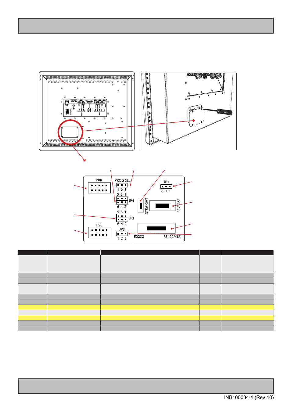
Comm settings
The communication options are set by dip switches and jumpers, placed at the backside of the unit. These switches/
jumpers are protected behind a hatch mounted with four screws. Unscrew those, and remove the hatch. The commu-
nication settings and its switches are illustrated below.
Factory Default Settings
The factory defaults are based on the configuration when ordered. To configure the unit back to its factory defaults,
please contact your provider.
Reference
Part number
Description
Type
Additional information
JP1
1-2 MENU BRT CONTROL
2-3 ALWAYS ON
MENU LED Brightness and ON/OFF Control
Jumper
Removal of this jumper will
deactivate key backlight.
INV LED and Power LED will
still be active though.
JP2
1-3 SCOM-A1
SCOM-A1 BEEPER- TO CHGND
Jumper
JP2
2-4 SCOM-A1
SCOM-A1 COM1-9 VIA 100R TO CHGND
Jumper
JP3
OPEN COM1-1=NC
OPEN COM3-11=NC
COM1-1 and COM3-11 pin select
Jumper
COM2-1 = 5V (ALWAYS)
JP4
1-3 SCOM-A1
SCOM-A1 = COM1/2-4 OPEN OR VIA 100R TO CHGND
Jumper
JP4
2-4 SCOM-A1
SCOM-A1 = COM1/2-6 OPEN OR VIA 100R TO CHGND
Jumper
S3
COM1/2 RS-232
RS-232 supported ONLY
Switch
RS-232 SUPPORT ONLY!
S4
STRAIGHT TX/RX
COM1/2 Straight or Crossed(Switched) TX/RX select
Switch
S5
RS422 FULL DUPLEX
COM1/2 FULL(RS422) or HALF(RS485) operation
Switch
NOT SUPPORTED!
PROG_SEL
PROGRAM U5
Program Select for programming U5 via PBR header
Jumper
PROG_SEL
PROGRAM U12
Program Select for programming U12 via PBR header
Jumper
Communication Protocol
Communication mode
Backlight Config
Program Select
RS422 Full Duplex ON/OFF
SCOM Config #1
Program
Input Connector
SCOM Config #2
COM Config
SCOM Config #2
S3
S4
S5