Resistors, Resistor values and markings – Elenco Electronic Component Kit User Manual
Page 5
-4-
RESISTORS
RESISTOR VALUES AND MARKINGS
The unit of measure for resistance is the ohm, which
is represented by the Greek letter
Ω. Before
technology improved the process of manufacturing
resistors, they were first made and then sorted. By
sorting the values into groups that represented a 5%
change in value, (resistor values are 10% apart),
certain preferred values became the standard for
the electronics industry. Table 1 shows the standard
values for 5% resistors.
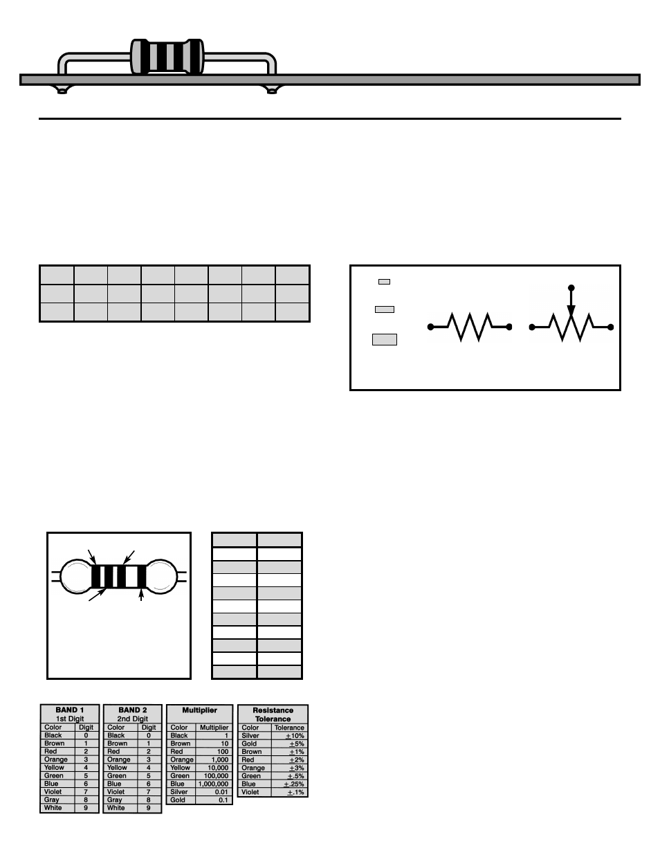
Resistors are marked by using different colored
rings around their body (see Figure 7). The first ring
represents the first digit of the resistor’s value. The
second ring represents the second digit of the
resistor’s value. The third ring tells you the power of
ten to multiply by. The final and fourth ring
represents the tolerance. For example, gold is for
5% resistors and silver for 10% resistors. This
means the value of the resistor is guaranteed to be
within 5% or 10% of the value marked. The colors
in Table 2 are used to represent the numbers from 0
to 9.
Note: If the third ring is gold, you multiply the first
two digits by 0.1 and if it is silver, by 0.01. This
system can identify values from 0.1
Ω to as high as
91 x 10
9
, or 91,000,000,000
Ω. The amount of power
each resistor can handle is usually proportional to
the size of the resistor. Figure 8 shows the actual
size and power capacity of normal carbon film
resistors, and the symbols used to represent
resistors on schematics.
10
11
12
13
15
16
18
20
22
24
27
30
33
36
39
43
47
51
56
62
68
75
82
91
Table 1
Figure 7
Orange
Red
Violet
Gold
27 X 10
3
= 27,000
Ω,
with 5% Tolerance
COLOR
VALUE
Black
0
Brown
1
Red
2
Orange
3
Yellow
4
Green
5
Blue
6
Violet
7
Gray
8
White
9
Table 2
Figure 8
Regular
Variable
Resistor Symbols
1/8 Watt
1/4 Watt
1/2 Watt