Mechanical parts, The electronic glue, The top legend – Elenco Electronic Component Kit User Manual
Page 23: Solder
-22-
MECHANICAL PARTS
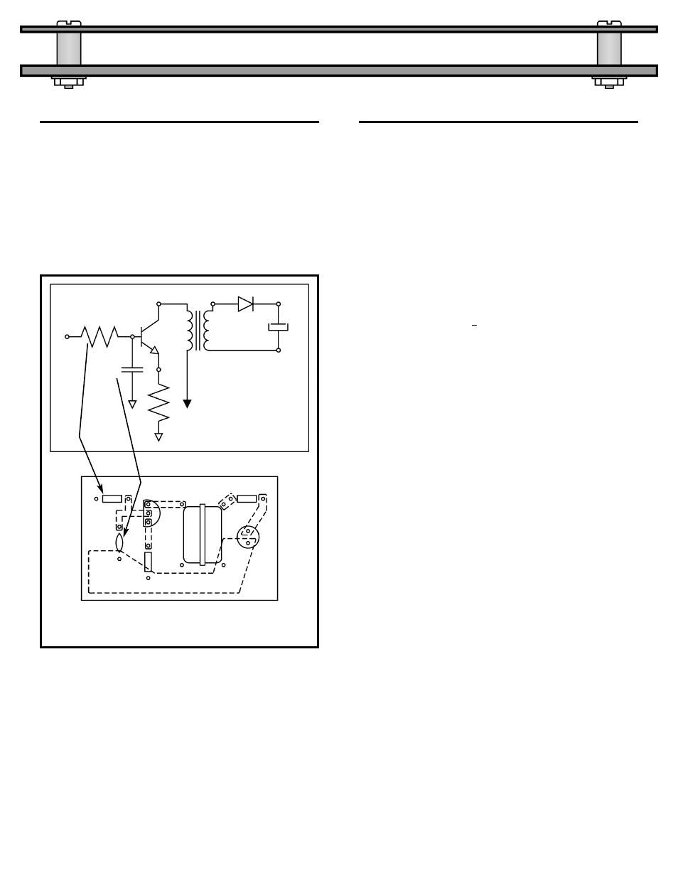
THE TOP LEGEND
The component side of a printed circuit board
should always have a drawing showing the
placement of the parts and their schematic marking
(R1, R2, etc.). This drawing is called the
Top
Legend. When a board needs to be repaired, the
schematic becomes the “road map” and the top
legend becomes the “address” on the part. Figure
35 shows the correlation between the Schematic
and the Top Legend.
Different parts have been discussed. A printed
circuit board to interconnect these parts has been
discussed. Now it’s time to talk about the “Electronic
Glue” called Solder. Soldering wire is composed of
Tin and Copper with a rosin or acid core. Acid core
solder should never be used on electronic boards
since the acid will damage the components. Acid
core solder is mainly used to attach metals (copper
water pipes for example). When tin and copper are
mixed, the melting point of the mixture is lower than
the melting point of either tin or copper. The point at
which the melting point is the lowest is when the
mixture equals 99.3% tin and 0.7% copper. This is
called the eutectic (u tek’tik) point of the mixture.
The most common flux placed at the center of this
hollow wire alloy is Rosin based. Removing the flux
from the board requires a chemical that can dissolve
rosin. In recent years many water soluble fluxes
have been developed. These fluxes can be removed
by washing the boards in water.
After the parts are placed in the holes on the printed
circuit board, their leads should be trimmed and
bent. A good mechanical connection will improve
the soldering capability of the parts by forcing the
part and copper on the board to rise to the same
temperature. Positioning the soldering iron correctly
and using the right amount of heat are crucial to a
good solder job. Solder practicing is highly
recommended (Elenco
®
Solder Practice Kit Model
SP-1A).
SOLDER,
The Electronic Glue
Figure 35
Schematic
Printed Circuit Board
R1
C1
R2
B+
T1
D1
C2
Q1
R1
C1
R2
T1
D1
C2
Q1