Capacitors, How is it calculated, Capacitance – Elenco Electronic Component Kit User Manual
Page 10: Capacitor values and markings, Figure 14, Figure 15
The amount of charge a capacitor can hold
(capacitance) is measured in Farads. In practice,
one farad is a very large amount of capacitance,
making the most common term used micro-farad or
one millionth of a farad. There are three factors that
determine the capacitance that exist between two
conductive plates:
1. The bigger the plates are (Surface Area),
the higher the capacitance. Capacitance
(C) is directly proportional to Area (A).
2. The larger the distance is between the two
plates, the smaller the amount of
capacitance. Capacitance (C) is indirectly
proportional to distance (d).
3. The larger the value of the dielectric
constant, the more capacitance (Dielectric
constant is equivalent to softness of the
rubber in our pipe analogy). The
capacitance (C) is directly proportional to
the Dielectric Constant (K) of the insulating
material. From the above factors, the
formula for capacitance in Farads becomes:
C = 0.244K Picofarads *
C = Capacitance in Picofarads (Farad x 10
-12
)
K = Dielectric Constant
A = Area of one Plate in square inches
N = Number of Plates
d = Distance between plates in inches
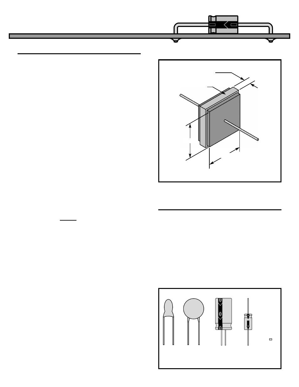
Example Calculation for Capacitor shown in Figure 14.
C = 2.24 x (1 x 1)(2 - 1) / (.01) = 224 Picofarads or
0.000224 Microfarads.
* If A and d are in centimeters change 0.224 to
0.0885.
The older styles of capacitors were marked with
colored dots or rings similar to resistors. In recent
years, the advances in technology has made it
easier to print the value, working voltage, tolerance,
and temperature characteristics on the body of the
capacitors. Certain capacitors use a dielectric that
requires markings to insure one lead is always kept
at a higher voltage than the other lead. Figure 15
shows typical markings found on different types of
capacitors. Table 4 gives the standard values used
and the different methods for marking these values.
-9-
CAPACITANCE,
How is it calculated?
CAPACITORS
A(N-1)
d
Figure 14
0.01 inch
Glass K=10
1 inch
1 inch
CAPACITOR VALUES AND MARKINGS
Figure 15
B
682K
K
+10
+16V
2200
μ
F 25V
10
μ
F 25V
Radial
Electrolytic
Axial
Electrolytic
Disc
Tantalum
Electrolytic
Chip
(no
markings)