Inductors, How is it calculated, How are they made – Elenco Electronic Component Kit User Manual
Page 15: Inductance, Μ a 10 l transformers
-14-
INDUCTORS
INDUCTANCE,
How is it calculated?
Reviewing how coils are made will show the
following:
1. Inductance of a coil is indirectly proportional to
the length of the coil.
2. Inductance is directly proportional to the cross
sectional area.
3. Inductance is proportional to the square of the
number of turns.
4. Inductance is directly proportional to the
permeability of the core material.
From the above information the formula for
inductance of a simple iron core would be:
L =
Where:
L = Inductance in microhenrys
N = Number of turns
μ = Permeability of core material
A = Cross-sectional area of coil, in square inches
l = Length of coil in inches
This formula is good only for solid core coils with
length greater than diameter.
N
2
μA
10
l
TRANSFORMERS,
How are they made?
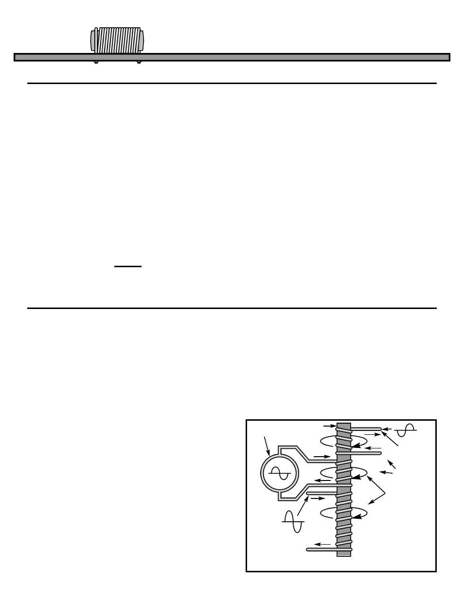
Placing different coils on the same iron core as
shown in Figure 22 produces the electronic
component known as the Transformer. If a DC
current is forced through the center coil, the other
two coils will only produce a current when the
original current is changing. Once the DC current
reaches a constant value, the other two coils will
“unlink” and produce no flowing current if loaded. If
the generator voltage is continuously changing as in
Figure 22, it will produce a current that changes with
time. This changing current in the center coil will
produce similar currents in both of the end coils.
Since the bottom coil has twice the number of turns
(twice the magnetic linkage), the voltage across this
coil will be twice the generator voltage. The power
in an electronic device is equal to the voltage across
the device times the current through the device
(P=VI). If the voltage doubles on the bottom
winding, then the current must become 1/2 due to
the law of conservation of power (Power cannot be
created or destroyed, but can be transformed from
one state to another). Since the bottom coil is
wound in the same direction as the generator coil,
the voltage across the coil (top wire to bottom wire)
will be the same polarity as the generator voltage.
The top coil is wound in the opposite direction
forcing the core magnet rotation (Called flux by the
Pros) to push the current in the opposite direction
and produce a voltage of the opposite polarity.
Since the number of turns in the top coil are the
same as the generator coil, the voltage and current
(Power that can be taken from the coil) will also be
equal. This ability to transform AC voltages and AC
currents influenced early experimenters to call this
device a Transformer.
Figure 22
Voltage
Generator
Iron Core
–V
Opposite
Voltage
i
i
½i
2V
2N Turns
N Turns
Direction of
Core Magnet
Rotation Due
to Current i