How are they made, Inductors – Elenco Electronic Component Kit User Manual
Page 14
-13-
INDUCTORS,
How are they made?
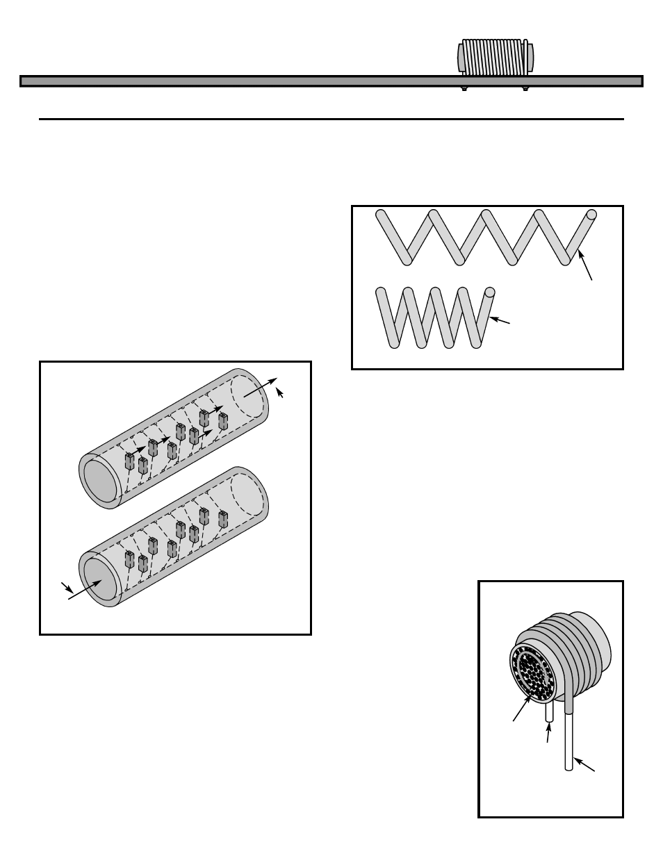
In order to understand how inductors are made, we
have to change our water pipe analogy slightly to
include the effect of magnetic fields. Consider two
pipes filled with water and small magnets attached
to the walls of the pipes with rubber bands as shown
in Figure 19. The moving magnets, due to the
original current, pull the magnets in the second pipe
and force a small current to flow in the same
direction as the original current. When the rubber
bands are fully stretched, the induced current will
stop, even though the initial DC current is still
flowing. If the original current is an AC current
however, it will induce a continuous AC current in the
second pipe because the magnets will move back
and forth, pulling the magnets in the second pipe
back and forth.
Consider the two coiled pipes shown in Figure 20.
When the pipe is stretched out (increased length) as
in coil 1, the adjacent turns have little affect on each
other. In coil 2 (decreased length) the magnets in
each turn of the pipe are linking and the amount of
“apparent mass” in the pipe seems to increase. In
an inductor, pushing the coiled wire closer together
causes the inductance of the coil to also increase,
and stretching the coil out will lower the inductance
of the coil. In other words, the inductance of a coil
is indirectly proportional to its length. If the diameter
of the coil is increased, it will take more hose to form
a loop, and the amount of water will therefore
increase. More water means a larger “apparent
mass”. Inductance will also increase in a coil if the
cross sectional area increases. Inductance is
directly proportional to area.
Consider the affect of adding more turns to coiled
pipe. The amount of material to push (mass) is
increased and the amount of linkage is increased
due to more magnets available. This causes the
“apparent mass” to increase at a greater rate than
would be expected. When making an inductor, the
actual inductance is directly proportional to the
square of the number of turns.
The final factor to consider when making a coil is the
core material at the center of the coil. If our pipe
wrapped around a material that contained many
magnets, they would also link to the magnets in the
pipe. This would increase the “apparent mass” of
the water in the pipe.
The tiny magnets in
the core would rotate
as shown in Figure 21
and force the water to
keep moving in the
same direction.
Placing an iron core at
the center of an
inductor will directly
increase the
inductance by an
amount equal to the
permeability of the
core material.
INDUCTORS
Figure 20
Figure 21
Coil 1
Coil 2
Many tiny
magnets
IN
OUT
Figure 19
Induced
Current
Initial
Current