Inductors – Elenco Electronic Component Kit User Manual
Page 16
-15-
TWO MORE LAWS ABOUT INDUCTORS
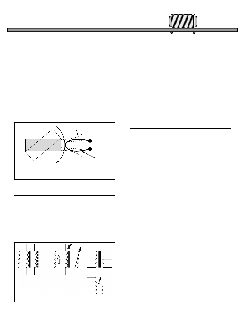
Faraday’s Law states that any time a conductor
moves through a magnetic field (Figure 23) a
voltage is generated. Because of this principle, it is
possible to attach a magnet (or coil) to a rotating
device and produce large amounts of electrical
power (the Hoover Dam for example).
Lenz’ Law states that the induced currents in a
conductor passing through a magnetic field will
produce a magnetic field that will oppose the motion
between the magnet and the conductor. To produce
a large amount of electrical power, a large
mechanical force is required (conservation of
power).
Most inductors are custom made to meet the
requirements of the purchaser. They are marked to
match the specification of the buyer and therefore
carry no standard markings. The schematic
symbols for coils and transformers are shown in
Figure 24. These symbols are the most commonly
used to represent fixed coils, variable coils, and
transformers.
The Q (figure of merit) of a coil is the ratio of the
inductive reactance to the internal series resistance
of the coil. Since the reactance and resistance can
both change with frequency, Q must be measured at
the desired frequency. Anything that will raise the
inductance without raising the series resistance will
increase the Q of the coil; for example, using an iron
core. Lowering the series resistance without
lowering the inductance will also raise the Q, more
turns of larger wire for example. Q is important
when the inductor is used in a resonant circuit to
block or select desired frequencies. The higher the
Q, the tighter the selection of frequencies become.
The Inductor prevents current from making any
sudden changes by producing large opposing
voltages. Magnetic coupling can be used to
transform voltages and currents, but power must
remain the same. Coils and transformers can be
used to select frequencies.
INDUCTORS
Figure 23
Wire
Lines of Flux
Motion of
Magnet
S
N
INDUCTANCE SYMBOLS AND MARKINGS
THE Q FACTOR IN COILS
SUMMARY
Figure 24
Fixed Coils
Variable Coils
Iron Core
Transformer
Tunable Transformer
X
L
r