Capacitors, Self test, Theory – Elenco Electronic Component Kit User Manual
Page 12: Practice, Extra credit
-11-
CAPACITORS
SELF TEST
1. A flow of electrons in one direction:
a) AC Voltage
c) Alternating Current
b) Direct Voltage
d) Direct Current
2. When two conductive plates are moved closer
together Capacitance will:
a) Increase
c) Stay the Same
b) Decrease
d) Vary Downwards
3. The name given to the material between a capacitor’s
plates:
a) Air
c) Conductor
b) Dielectric
d) Insulator
4. Electrons flowing in and out of a wire:
a) AC Voltage
c) Alternating Current
b) Direct Voltage
d) Direct Current
5. If the size of the conductive plates is increased,
capacitance will:
a) Increase
c) Stay the Same
b) Decrease
d) Vary Downwards
6. A capacitor will block:
a) AC Voltage
c) Alternating Current
b) Direct Voltage
d) Direct Current
7. When electrons are forced onto one plate of a
capacitor:
a) Polarization
c) Storage
b) Discharging
a) Charging
8. A capacitor lead that is marked with a + must always be:
a) Grounded
c) At higher voltage than
the other lead
b) At highest voltage
d) b & c
9. A small disc capacitor marked 100 has a value of:
a) 100
μF
c) 100pF
b) .00001F
d) 100F
10. A large electrolytic capacitor marked 100 has a value
of:
a) 100
μF
c) 100pF
b) .00001F
d) 100F
11. If a dielectric is changed from air to distilled water the
capacitance will:
a) remain the same
c) decrease
b) increase 81 times
d) drop in half
12. A dielectric that stores energy with no loss:
a) Does not exist
c) Pure Glass
b) Air
d) A perfect vacuum
THEORY
Circle the letter that best fits the description.
PRACTICE
Open the bag marked “capacitors” and fill in the table below.
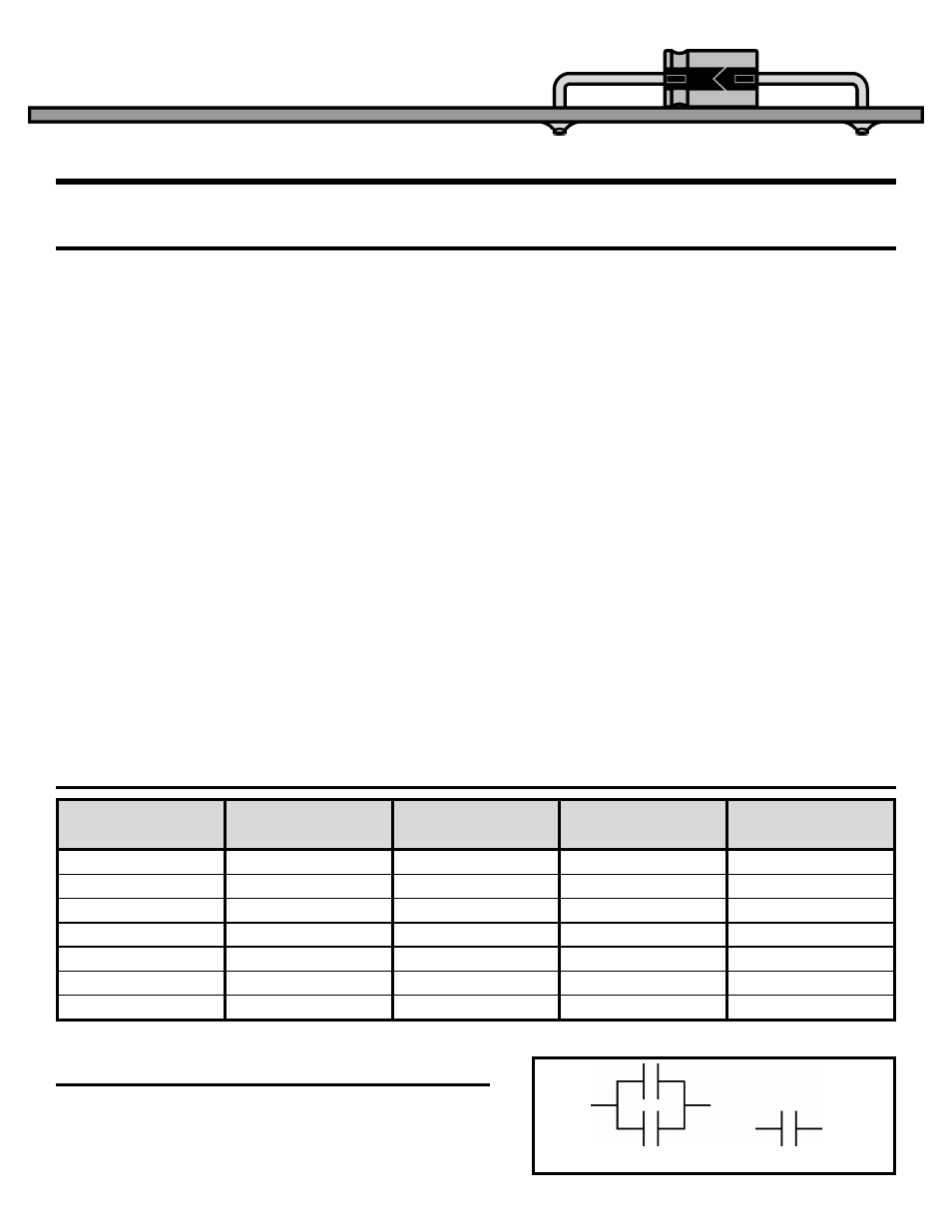
EXTRA CREDIT
What happens to the total capacitance if you connect two
capacitors as shown in Figure 17. Hint, use water pipe
analogy and try to calculate equivalent if one water pipe.
Type
Capacitance
Value
Working
Voltage
Polarized
(Y/N)
Other
Markings
Figure 17
10
μF
20
μF
?
μF
Table 4