Elenco Snap Circuits SnapMicro I Deluxe ® User Manual
Page 71
70
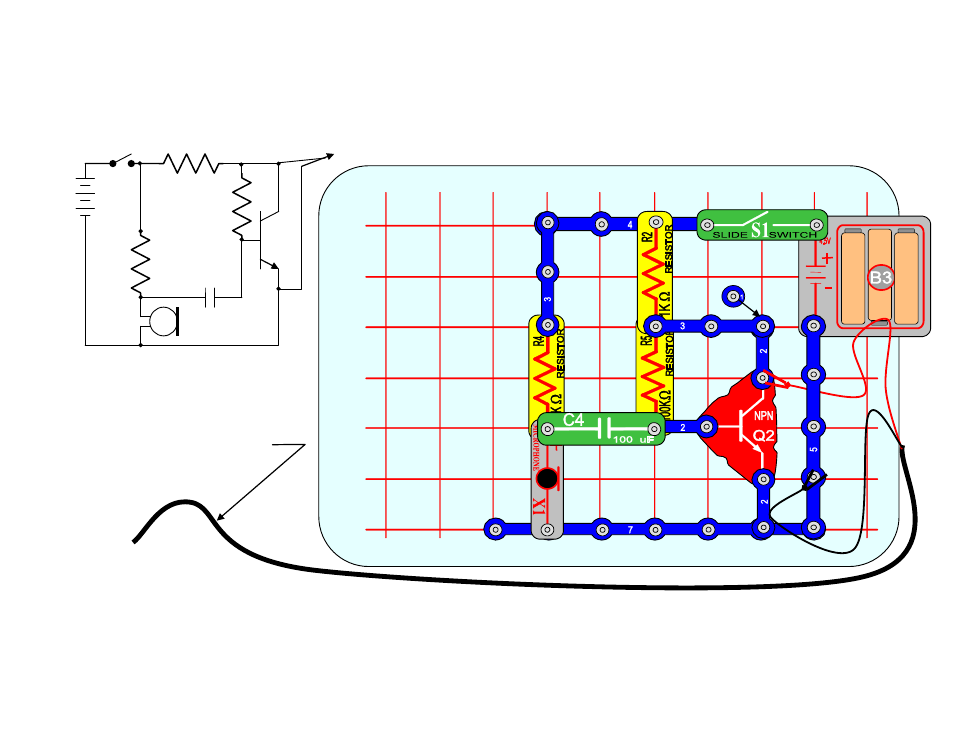
PROJECT 20, Audio Amplifier and the Microphone (X1)
Build the Snap Circuit shown below. For those familiar with electronic circuits and
schematics a drawing of this circuit is also included.
Schematic Drawing
Make sure the computer speakers are turned on and the volume or loudness control is not at zero.
Also make sure the microphone input is on by checking the controls as shown on the next page.
R2 1K
R4 10K
R5 100K
C4 100uf
X1 Microphone
Q2
NPN
B3
4.5V
S1 Switch
TO MICROPHONE INPUT ON COMPUTER
B
C
D
E
F
2
3
4
5
6
A
G
1
7
8
9
10
2
1
2
1
2
2
1
2
TO COMPUTER
Microphone Input
1
3
1
2
2
3
MICROPHONE CABLE
1
1
2
2
This manual is related to the following products:
See also other documents in the category Elenco Toys:
- Upgrade Kit SC100 to SC300 (76 pages)
- Snap Circuits Jr.® Educational 100 Exp. (48 pages)
- Upgrade Kit SC300 to SC500 (64 pages)
- Snap Rover ® (24 pages)
- XP&trade (64 pages)
- Snap Circuits LIGHT ® (84 pages)
- Snap Circuits Extreme® Educational 750 Exp. (88 pages)
- Projects PC1-PC73 (60 pages)
- Electronics 202 (132 pages)
- Snaptricity® (92 pages)
- Upgrade Kit SCROV10 to SCROV50 (48 pages)
- Snap Circuits Green ® (80 pages)
- C Adapter for Snap Circuits® (2 pages)
- Motion Detector Kit (20 pages)
- Digital Roulette Kit (16 pages)
- FM Wireless Microphone Kit (12 pages)
- AM Radio Kit (32 pages)
- AM Radio Kit (36 pages)
- AM/FM Radio Kit (64 pages)
- Circuit Maker Skill Builder 125 (64 pages)
- Circuit Maker Sound Plus 200 (80 pages)
- Understanding Logic Gates (16 pages)
- Understanding Logic Gates and Circuits (42 pages)
- Tumbling Robot (12 pages)
- Solar Energy (16 pages)
- C2D Scope (16 pages)
- 288x Astrolon Telescope with Aluminum Tripod (1 page)
- Simulated Frog Dissection Kit (1 page)
- Talking Galaxy Planetarium with Night Light (1 page)
- Night’n Day® (10 pages)
- Radio Controlled Black Widow (1 page)
- Handheld Microscope (2 pages)
- Water Filtration Kit (8 pages)
- 6-in-1 Solar Kit (18 pages)
- Microscope Set in Carrying Case (1 page)
- Mobile 20 Telescope (1 page)
- Mechanical Drum (20 pages)
- Aerial Screw (20 pages)
- Swing Bridge (20 pages)
- Printing Press (24 pages)
- MultiBarrel Cannon (20 pages)
- Armored Car (24 pages)
- Paddleboat (20 pages)
- SelfPropelled Cart (20 pages)
- Catapult (24 pages)