Project 2: adding amplifier & loudness control – Elenco Snap Circuits SnapMicro I Deluxe ® User Manual
Page 25
24
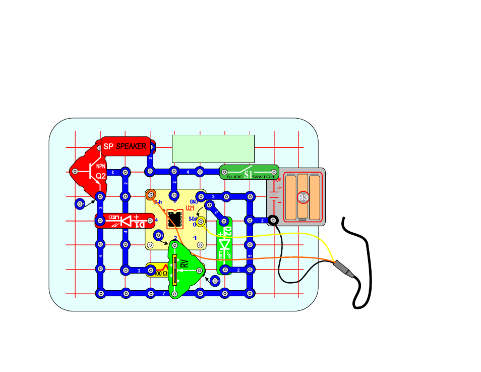
PROJECT 2: ADDING AMPLIFIER & LOUDNESS CONTROL
Modify the Snap Circuit
®
from the previous project to look like the circuit below. The variable resistor RV
will be used to increase and decrease the audio level. The NPN transistor ‘Q2’ is used to amplify the
power to the speaker ‘SP’. LED ‘D2’ is still disconnected during programming but will flash if the Yellow
programming wire is removed and the ‘2 Snap’ is connected to S-Out or pin 0.
Assuming the micro-controller is still programmed to play and flash the lights, connect the ‘2 snap’,
switch ‘S1’ to “ON” and test the circuit.
Use the loudness control to adjust audio level for desired loudness.
B
C
D
E
F
2
3
4
5
6
A
G
1
7
8
9
10
After programming
remove Yellow lead and
attach 2 Snap.
1
2
1
1
1
1
1
1
1
1
2
2
2
2
2
2
2
2
2
2
2
2
3
2
1
3
To Computer
2
1