Project 12 – the dc motor/generator – Elenco Snap Circuits SnapMicro I Deluxe ® User Manual
Page 49
48
PROJECT 12 – THE DC MOTOR/GENERATOR
Brushes
Because DC motors use brushes and act as generators they may produce voltages that interfere with
the micro-controller program. The DC motor provided with your Snap Circuits
®
parts was picked to
reduce this problem. The following circuit will test the program while motor is running with and without a
load.
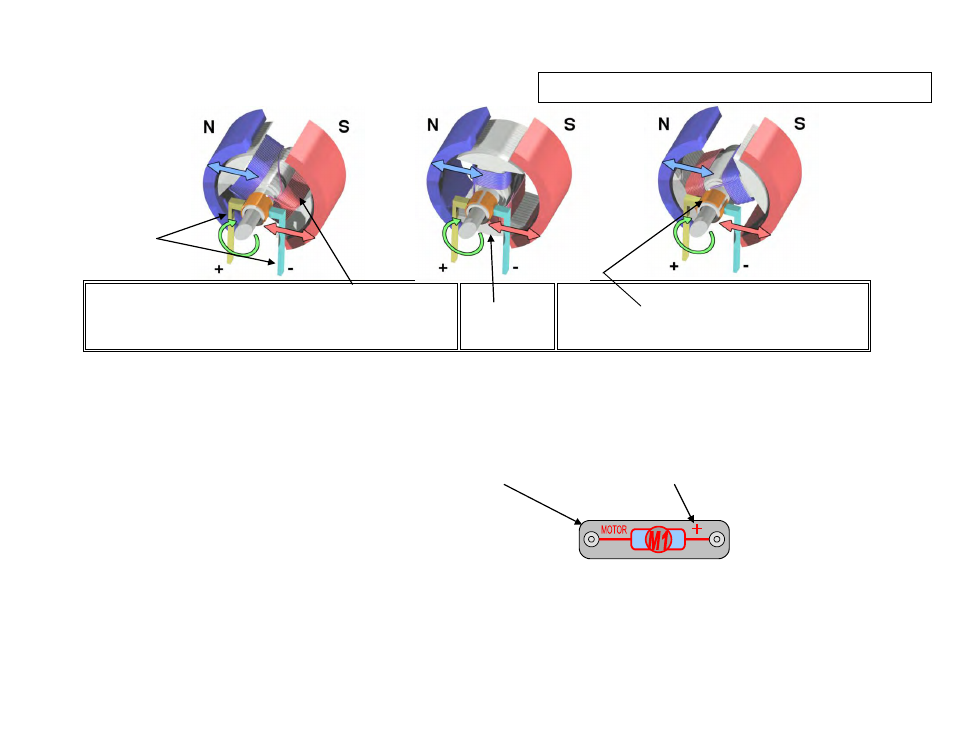
The following symbol is used to represent the DC Motor. Pay attention to the “+” sign since it will
determine the direction of rotation when power is applied.
Build the circuit shown on the next page and open the
program editor to make the flow chart that follows.
Convert flow chart to the basic program shown. Use only fresh alkaline batteries in this project.
A simple DC electric motor. When the coil is powered, a
magnetic field is generated around the armature. The left side
of the armature is pushed away from the left magnet and
drawn toward the right, causing rotation.
The armature
continues to
rotate.
When the armature becomes horizontally aligned,
the commutator reverses the direction of current
through the coil, reversing the magnetic field. The
process then repeats.
The information shown here was reproduced from the web site;
http://en.wikipedia.org/wiki/Brushed_DC_Electric_Motor#Simple_Two_Pole_DC_Motor