Elenco Snap Circuits SnapMicro I Deluxe ® User Manual
Page 7
6
Build the circuit shown below. Snap Circuit
®
Boards are built one level at a time. The base grid is
considered to be level 0. Parts placed directly on the base grid are said to be on level 1 and will have a
small black 1 next to the part. Parts placed on level 1 parts are said to be on level 2 and will have a
small black 2 next to the part. This process is continued until all parts are installed.
1. Turn Switch S1 to ON and the LED should
glow red. Turn S1 to OFF.
2. Turn D1 around so the + is on the switch
side and repeat step 1. In this case the
LED should be dark and never glow. Turn
Switch S1 to OFF and replace LED ‘D1’ in
the original position.
3. Replace the 1k resistor ‘R2’ with a
100 resistor ‘R1’. The LED ‘D1’ should
be brighter when Switch ‘S1’ is turned ON.
Lower resistance produces more current,
and more current makes LED’s glow
brighter.
4. Use this circuit to test LED’s, resistors, and
switches S1 and S2.
The SPEAKER ‘SP’
is actually an 8 speaker
that can be used to produce audible tones.
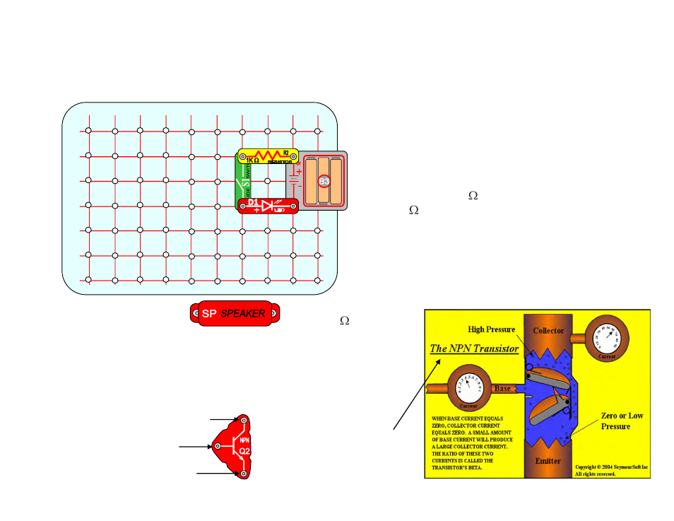
The NPN Transistor ‘Q2’ is a device that amplifies current. For
example, a small current from base to emitter will produce a
much larger current from collector to emitter. The NPN
connections are labeled collector, base, and emitter as shown
here.
B
C
D
E
F
2
3
4
5
6
A
G
1
7
8
9
1
0
1
1
2
2
BASE
EMITTER
Similar device in
water pipe system
COLLECTOR