Experiment #45: the flip-flop – Elenco Electronic Playground 50-in-1 Experiments User Manual
Page 64
-64-
This circuit is yet another variation of the basic
multivibrator configuration. Connect the wires according
to the Wiring Checklist. One LED will be on, the other off.
Take the loose wire and touch it to the base of the
transistor that is on (spring 15 or 18). That transistor
turns off and the other turns on. Do this a few more times
until you see that touching the “on” transistor base “flips”
the transistors and the LEDs. You might say that the
transistor turning on “flips” and the one turning off “flops”.
Notice that touching the “off” transistor base has no
effect.
This circuit is called formally known as the bistable
switch, but is nicknamed the “flip-flop” due to the way it
operates. The name flip-flop may seem silly to you at
first, but variations of this circuit form one of the basic
building blocks for digital computers. This circuit can be
thought of as a memory because it only changes states
when you tell it to, it “remembers” what you told it to do
even though you removed the loose wire. By combining
several of these circuits you can remember a letter or
number. By combining thousands of these circuits a
computer can remember a small book. A typical
computer has many thousands of flip-flops, all in
integrated circuit form. The operation of this circuit is
simple. If NPN1 is on then it will have a low collector
voltage. Since this collector voltage also connects to
NPN2’s base, NPN2 will be off. But if you ground NPN1’s
base then it will turn off and its collector voltage rises,
turning on NPN2. NPN2 will stay on until you ground its
base.
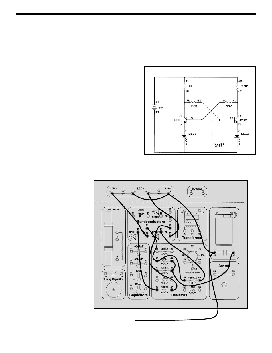
EXPERIMENT #45: The Flip-Flop
Wiring Checklist:
o 16-to-40-to-51
o 52-to-18
o 19-to-42-to-47
o 46-to-15
o 17-to-1
o 20-to-3
o 2-to-4-to-26-to-unconnected
o 41-to-43-to-27
Schematic
Loose Wire