Experiment #20: battery immunizer – Elenco Electronic Playground 50-in-1 Experiments User Manual
Page 34
-34-
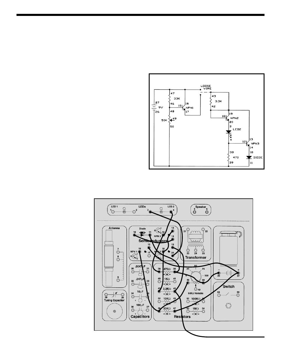
Connect the wires according to the Wiring Checklist and
schematic. Note that the collectors of NPN2 and NPN3
are not connected although their wires cross over each
other in the schematic. Connect the loose wire from
spring 43 (3.3K
Ω) to spring 16 (NPN1 collector, or 9V);
the LED is bright. Now connect the wire to spring 17
(NPN1 emitter) instead of spring 16; the LED is just as
bright. So we made a change and nothing happened,
does this seem like a dull experiment? It may seem dull
but the important idea here is that we made a big change
to the circuit but nothing happened to the LED.
Take a look at the schematic. The circuit to the left of the
loose wire reduces the voltage to 4.7V. You connect the
loose wire to either the 9V battery voltage or the modified
4.7V. The circuit to the right of the loose wire creates a
fixed current to the LED, which will not change even if the
voltage (9V or 4.7V) to the circuit changes. So when you
changed which voltage the loose wire was connected to
you didn’t see any change in LED brightness.
In case you’re not convinced by this, let’s change the
circuit to prove it. Place LED2 in series with the 3.3K
Ω
resistor (remove the wire from spring 42 and connect it to
spring 2, and add a wire from spring 1 to spring 42). Now
connect the loose wire to the two voltages as before and
you should see LED2 change between bright and dark
while LED1 remains bright as before.
You could use a circuit like this when you don’t want your
performance to be affected as your voltage drops,
perhaps due to a battery weakening over a long period of
use. So you could say your circuit is immune to
(protected against) a weak battery.
EXPERIMENT #20: Battery Immunizer
Wiring Checklist:
o 16-to-27-to-47
o 15-to-46-to-48
o 26-to-50-to-39-to-11
o 10-to-14
o 4-to-12-to-38
o 3-to-20
o 13-to-18-to-42
o 19-to-43-to-unconnected
Schematic
Loose
Wire