Experiment #39: radio announcer – Elenco Electronic Playground 50-in-1 Experiments User Manual
Page 58
-58-
Now that you’ve built an AM receiver, how about building
an AM transmitter? Ever wanted to be a radio
announcer? You’re about to get your chance. Note: you
need an AM radio for this experiment.
Connect the wires according to the Wiring Checklist,
connecting the battery wire last since this will turn on the
circuit. As in the last experiment you will get better circuit
performance if you keep your wires short, so don’t use
longer wire lengths than you need to.
Take an AM radio you have in your home, turn it on,
extend its antenna, and place it next to your Electronic
Playground. Tune it to the low end of the AM frequency
range or somewhere near the low end where there is only
static and no radio station. Now slowly adjust your
variable capacitor until you hear the static quiet down or
you hear a hum instead. This indicates to you that your
radio is receiving the transmitted signal from your
Playground, so both must be on the same frequency. Tap
the cardboard panel near the speaker, you should hear
this on the radio. Turn the radio volume control up a little
if you don’t hear it at first. If you can’t get your radio and
Playground to be on the same frequency then try tuning
the radio to a different frequency (stay near the low end
of the radio’s tuning range) and try again. The AM
transmitter circuit you are using is a very simple one and
it will not operate across the entire range of AM radio
frequencies. Your radio may have been tuned to a
frequency that your transmitter can’t reach. You can also
tune your radio while tapping near the speaker. When
you hear the tapping then your Playground and radio are
on the same frequency (if this happens to be where an
AM station exists then tune Playground and radio to the
nearest static spot). If you still can’t get this to work then
check your circuit wiring. This is the most complex circuit
you will build, and it is easy to make wiring errors.
Now talk into the speaker, keeping your mouth close to it.
You should hear yourself on the radio! Turn up your radio
volume control or shout if you don’t hear yourself at first.
You can also adjust your variable capacitor slightly to
make sure you are tuned for best transmission.
In this experiment the speaker is being used as a
microphone. A microphone is the opposite of a speaker,
converting sound waves into electrical energy by sensing
the variations in air pressure. (Recall from Experiment 27
that sound waves are variations in air pressure). The
mechanical construction of the speaker allows it to also
be used as a microphone, though it is more efficient as a
speaker than as a microphone. If your voice didn’t sound
very clear on the radio, it is probably because of the
speaker’s limitations as a microphone. The transformer is
used with the speaker as before.
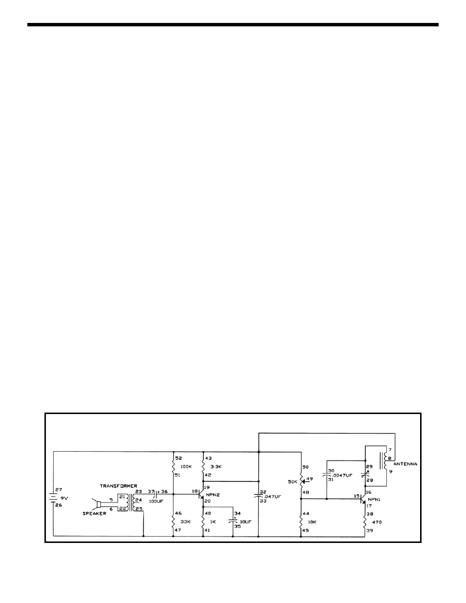
The circuit is complex but advanced students may want
to take a look at the schematic. The signal from the
speaker (microphone) and transformer is applied to a
high gain amplifier built around NPN2. This is the
standard application of the transistor circuit you used in
Experiment 16. The four resistors turn on the transistor
but do not saturate it. The circuit built around transistor
NPN1 is an oscillator, similar to the ones you have been
using only higher in frequency. It uses the antenna as its
inductor instead of the transformer, uses the variable
capacitor to adjust the frequency, and it uses four
resistors (including the 3.3K
Ω) to turn on the transistor
without saturating it. It also gets its power from the output
of the NPN2 circuit instead of directly from the battery.
This is how the high-frequency oscillator is amplitude
modulated to carry your voice to the radio. Part of the
oscillator energy is transferred into the air at the antenna.
Now you can use this circuit to be a radio announcer or
DJ!
EXPERIMENT #39: Radio Announcer
Schematic