Leaders in actuation – Bimba PFC-LRT User Manual
Page 9
Leaders in Actuation.
Bimba Manufacturing Company
Monee, IL 60449-0068
Telephone: 708.534.8544
Email: [email protected]
www.bimba.com
Rev Level: 0
T
o learn more about this
product, scan this QR code
with your mobile device.
The information presented is in Bimba’s best engineering opinion and should be used for reference only. Recommendations derived should be verified under
actual operating conditions. Bimba reserves the right to change specifications without prior notice.
9
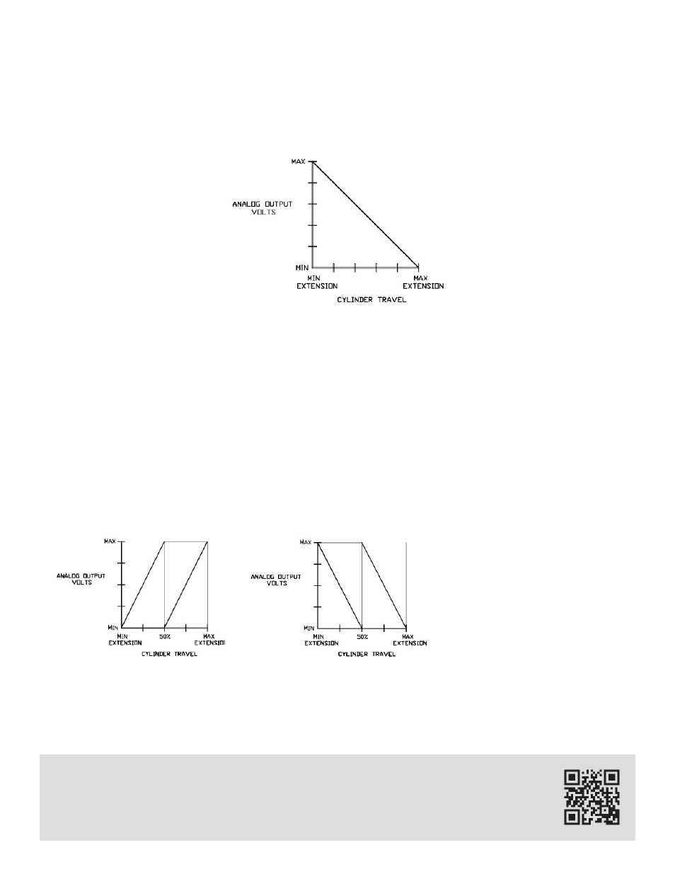
For some applications it may be desirable to reverse this operation and have maximum analog output at
minimum extension and minimum output at maximum extension. This can be achieved by switching the
wires at Terminals 3 and 5 of the control unit as shown before in FIGURE 2.
The resulting output action is opposite from standard (FIGURE 6). FIGURE 7 illustrates this reversed out-
put action.
B. Scaling the Output
Scaling is a feature that allows a unit's output boundaries to be adjusted to individual application needs.
The minimum analog output point (offset) is adjustable, as well as the distance from minimum output that
the cylinder must travel until maximum analog output is achieved (this will be referred to as “gain” from
here on). The output boundaries provide minimum and maximum output with linear output between the
two limits.
FIGURE 8 illustrates the allowable output adjustment range for standard output operation as a percent-
age of full cylinder extension. FIGURE 9 illustrates the allowable output range for reversed output opera-
tion. The shaded region of each graph represents the allowable area.
The figures illustrate two impor-
tant facts.
1. The maximum offset that the
minimum output point can have
is 50% of cylinder stroke.
2. The smallest “gain” range can
be no less than 50% of cylinder
stroke.
The figures illustrate several ac-
ceptable output schemes and
then several improper output
schemes for a 12" cylinder.
FIGURE 7
REVERSED ANALOG OUTPUT
FIGURE 9
REVERSED OUTPUT RANGE
FIGURE 8
STANDARD OUTPUT RANGE