Leaders in actuation – Bimba PFC-LRT User Manual
Page 17
Leaders in Actuation.
Bimba Manufacturing Company
Monee, IL 60449-0068
Telephone: 708.534.8544
Email: [email protected]
www.bimba.com
Rev Level: 0
T
o learn more about this
product, scan this QR code
with your mobile device.
The information presented is in Bimba’s best engineering opinion and should be used for reference only. Recommendations derived should be verified under
actual operating conditions. Bimba reserves the right to change specifications without prior notice.
17
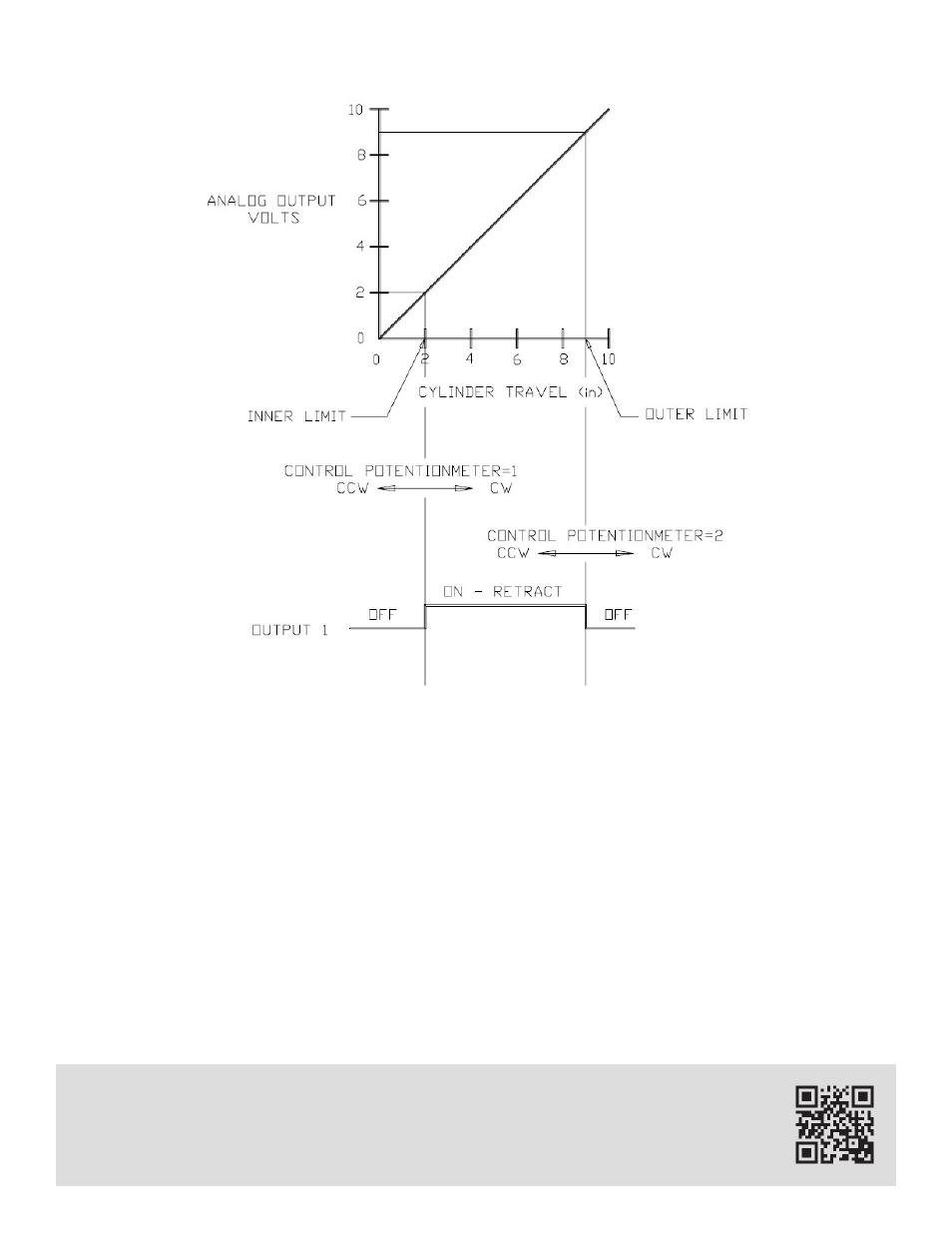
By using the Continuous Cycle Mode of the controller, a continuous cycling process can be obtained.
The N.O. contact of Relay 1 is the only output necessary for cycling. The control potentiometers are
used for setting the inner and outer limits of the stroke. At each limit the cylinder will reverse direction and
move toward the other limit. This process will continue indefinitely until interrupted.
FIGURE 16 illustrates Relay 1 operation and the ideal voltage output versus cylinder travel (seen at Ter-
minals 6 and 7). Control potentiometer 1 is used to set the inner limit (2") and control potentiometer 2 is
used to set the outer limit (9"). The cylinder will extend while the N.C. contact of Relay 1 is closed. When
the cylinder reaches the outer limit, the N.O. contact of Relay 1 will close. When this happens, power is
applied to the solenoid causing the cylinder to retract. When the inner limit is reached, the relay returns
to normal and the process repeats itself.
FIGURE 16