Leaders in actuation – Bimba PFC-LRT User Manual
Page 21
Leaders in Actuation.
Bimba Manufacturing Company
Monee, IL 60449-0068
Telephone: 708.534.8544
Email: [email protected]
www.bimba.com
Rev Level: 0
T
o learn more about this
product, scan this QR code
with your mobile device.
The information presented is in Bimba’s best engineering opinion and should be used for reference only. Recommendations derived should be verified under
actual operating conditions. Bimba reserves the right to change specifications without prior notice.
21
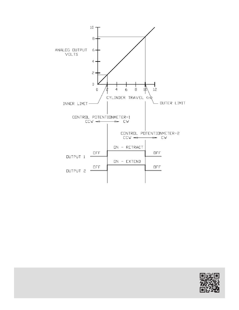
By using the Continuous Cycle Mode of the controller, the cylinder will continually cycle between the two
set point limits. In this case, there will be 8" of piston travel in each direction to perform the desired task.
FIGURE 20 illustrates the output actions and the ideal voltage output versus piston travel (seen at Ter-
minals 6 and 7). Control potentiometer 1 is used to set the inner limit (2") and control potentiometer 2
is used to set the outer limit (10"). Relay 1 will be on while the cylinder is retracting to the inner limit (2").
When the piston reaches the inner limit, Relay 1 will shut off and Relay 2 will be energized. Relay 2 will
cause the cylinder to extend until the piston reaches the outer limit (10"), where Relay 1 will turn on and
the process will repeat.
FIGURE 20