Leaders in actuation – Bimba PFC-LRT User Manual
Page 7
Leaders in Actuation.
Bimba Manufacturing Company
Monee, IL 60449-0068
Telephone: 708.534.8544
Email: [email protected]
www.bimba.com
Rev Level: 0
T
o learn more about this
product, scan this QR code
with your mobile device.
The information presented is in Bimba’s best engineering opinion and should be used for reference only. Recommendations derived should be verified under
actual operating conditions. Bimba reserves the right to change specifications without prior notice.
7
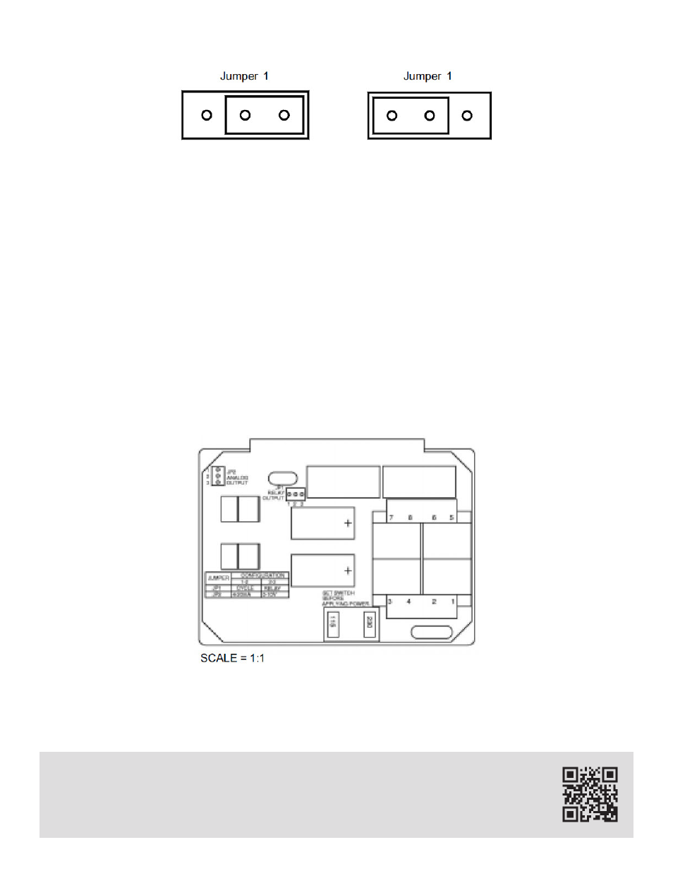
2. Continuous Cycle Mode
To activate the Continuous Cycle Mode, move Jumper 1 to Position B (See FIGURE 4). This enables the
Continuous Cycle Mode and disables the Independent Relay Mode.
As one output turns on, the other turns off and vice-versa (See FIGURE 3). This mode of operation al-
lows for continuous cycling of a cylinder between two adjustable limits. Set Point 1 control potentiometer
is used to set the inner limit and Set Point 2 control potentiometer is used to set the outer limit. Set Point
1 must be less than Set Point 2.
In this mode of operation, the load is connected to the Normally Open (NO) side of the relays; pins 10
and 13 in FIGURE 2. This means an output is turned on as the analog output is greater than its set point
and turned off as the analog output drops below its set point.
FIGURE 4
OPERATING MODE SELECTION
Position B
CONTINUOUSLY CYCLE MODE
Position A
INDEPENDENT RELAY MODE
JP1
Relay
Output
1
2
3
1
2
3
FIGURE 5
CIRCUIT LAYOUT